On December 1st, the Repair Course for Small Laboratory Equipment, taught by our engineers at the EDIBON facilities, was completed, lasting 4 days.
The attendees, (Laboratory technicians and maintenance of the Rey Juan Carlos University of Madrid) had the opportunity to perform multiple...
N-M13 Basic Sequential Circuits Module
INNOVATIVE SYSTEME
With Basic Sequential Circuits Module, "N-M13", designed by EDIBON, all types of bistables, counters, flip-flops, synchronous sequential circuits and the operation of memories can be studied.
Erweiterungen
ÄHNLICHE NEUIGKEITEN
ALLGEMEINE BESCHREIBUNG
Logic gates and the circuits created with them constitute combinational logic, so called because the output only depends on the combination of the input variables present.
There is a second group of logic circuits called sequential logic, so called because the output depends, in addition to the input variables, on the value previously present at the output. This means that these circuits are equipped with memory. In addition, a large proportion of sequential circuits are only activated by a cyclic or clock signal and are called synchronous sequential circuits.
The edge trigger time can last for the duration of the clock signal (pulse trigger) or the instant of change from 0 to 1 (edge trigger).
In the elements activated by edge, a small triangle is drawn on the clock connection, which is completed with a circle to specify that the edge is falling (this is the most frequent activation).
For the study of sequential circuits, use is made of the chronogram, the graphic representation of how both the inputs and the output of the circuit evolve over time:
Basic sequential circuits are called bistables, scales or flip-flops.
With Basic Sequential Circuits Module, "N-M13", designed by EDIBON, all types of bistables, counters, flip-flops, synchronous sequential circuits and the operation of memories can be studied.
In addition, faults can be simulated in most of the circuits under study. The student must investigate what is happening in the circuit and why it is not working properly. These faults simulations can be of several types from damage components to a hypothetical incorrect circuit assembly.
ÜBUNGEN UND GEFÜHRTE PRAKTIKEN
GEFÜHRTE PRAKTISCHE ÜBUNGEN IM HANDBUCH ENTHALTEN
Bistables:
- Bistables.
- Bistable S-R using NAND gates.
- Practical performance.
- Faults study in the Bistables.
- Theoretical/practical exercises.
Shift registers:
- Shift registers.
- Faults study of the shift registers.
- Theoretical/practical exercises.
Counters:
- Steps to be followed for the assembly of a counter.
- Faults study of the counters.
- Theoretical/practical exercises.
Synchronous Sequential Circuits:
- Practice of the synchronised.
- Faults study of the Synchronised sequential circuits.
- Theoretical/practical exercises.
Memories:
- Theoretical/practical exercises.
MEHR PRAKTISCHE ÜBUNGEN FÜR DAS GERÄT
- Several other exercises can be done and designed by the user.
ERGÄNZENDE AUSRÜSTUNG
14.2.1.6.- LEISTUNGSELEKTRONIK
LIEBA
We present a flexible and modular-based system for learning basic electronics, basic electricity and circuit theory. The advantage given by this learning and teaching system is that the student establishes his own rhythm, thus rendering...
2.3.3.- DIGITALE ELEKTRONIK
N-M60
Analog/Digital Converters Module
Most of the "information" generated in the world by various physical phenomena has a strong analogical character. This means that the information undergoes a continuous variation within certain limits determined over time. Of course, there is also...
2.3.3.- DIGITALE ELEKTRONIK
N-M61
Digital/Analog Converters Module
Digital/analog conversion happens when you want to recover or re-obtain a digital signal that has been processed and we want to regenerate it. A signal that has been sampled, for example, a temperature signal and we need to return it to the...
14.2.1.3.- DIGITALE ELEKTRONIK
N-M10
Digital Systems & Converters Module
Generally, an analog to digital converter is an electronic device that converts an analog voltage input to a digital number.digital number. The digital output can use different coding schemes, such as binary, although some non-electrical or...
14.2.1.3.- DIGITALE ELEKTRONIK
N-M11
Digital Electronics Fundamentals Module
Digital systems are systems for processing, treatment or transmission of information, in which such information is limited to take values in a discrete set. These signals (whose magnitude can only take one value from a discrete set of values) are...
14.2.1.3.- DIGITALE ELEKTRONIK
N-M12
Basic Combinational Circuits Module
A combinational circuit is an electronic circuit in which the value of its outputs at a given instant, depends on the value of the inputs at the same instant. In other words, it is a circuit that has no memory. Combinational circuits work with...
14.2.1.3.- DIGITALE ELEKTRONIK
CADDA
Computergesteuerte A/D- und D/A-Wandlereinheit (PC)
The Computer Controlled A/D and D/A Converters Unit, "CADDA", unit has been designed to help the students to learn how to perform the most common procedures and study the different circuits used to convert analog signals in a digital signals and...
14.2.1.3.- DIGITALE ELEKTRONIK
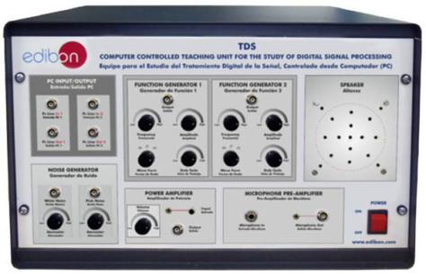
TDS
Computergesteuerte Lehreinheit zum Erlernen der digitalen Signalverarbeitung
The Teaching Unit for the Study of Digital Signal Processing "TDS" allows to study the principles and more important concepts about digital signal processing, including study and practical exercises, among others, of:Continuous waveforms...