PB2C Mehrpumpen-Prüfstand (2 Pumpentypen), computergesteuert (PC)
INNOVATIVE SYSTEME
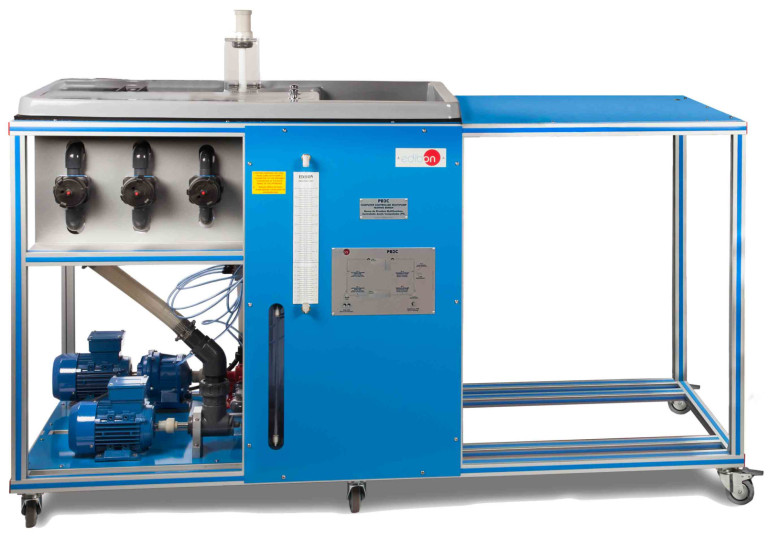
The Computer Controlled Multipump Testing Bench (2 types of pumps), "PB2C", allows the students to study the operating characteristics of the centrifugal and gear pumps.
Erweiterungen
Laboratorien
ÄHNLICHE NEUIGKEITEN
ALLGEMEINE BESCHREIBUNG
The Computer Controlled Multipump Testing Bench (2 types of pumps), "PB2C", allows the students to study the operating characteristics of the centrifugal and gear pumps. This unit allows to control and to measure the most representative parameters of the pumps.
The measurements that can be taken using the unit are: admission and discharge pressure of the pump, impelled water flow, torque and turning speed of the pump and the manometric height, the hydraulic and mechanic power and the efficiency can be determined.
The unit is mounted on a structure with a working surface covered by a plastic sheet. Two different parts can be distinguished in the unit: the pumps, with their motors, connections and flexible hoses and the tanks to store and recycle water, with their measuring elements.
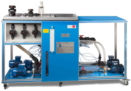
The minimum supply includes two types of pumps: one centrifugal pump and one gear pump. There are several optional pumps (not included in the minimum supply) that can be connected to the unit through valves and flexible hoses in order to demonstrate the operating behavior of these pumps.
Each pump is activated by a separate motor which allows the direct measurement of the torque. The speed is changed by a frequency converter, located in the control interface box, and computer controlled.
The pump under study impels water in a closed circuit. There are two pressure tappings in each pump, one at the admission and other at the discharge of the pump, to determine the manometric head of the different pumps. These tappings are connected to their corresponding pressure sensor.
The pumps included in the minimum supply are connected through flexible hoses to the volumetric tank and to the storage tank. The connection of the optional pumps to the volumetric tank and the storage tank are done through valves, connections and flexible hoses.
The unit includes two tanks, located at different levels, to recycle the water. The upper volumetric tank, located just over the water storage tank, is equipped with two weirs and two stilling baffles and includes a discharge valve and an activator.
The volumetric tank has been designed to accommodate low or high flows and it includes a level sensor to determine the water flow and the water level in the volumetric tank, an indicating transparent tube and a graduated scale. It has a safety overflow system that directly pours water into the storage tank if an incorrect use is made. The storage tank includes an indicating transparent tube.
This Computer Controlled Unit is supplied with the EDIBON Computer Control System (SCADA), and includes: The unit itself + a Control Interface Box + a Data Acquisition Board + Computer Control, Data Acquisition and Data Management Software Packages, for controlling the process and all parameters involved in the process.
ÜBUNGEN UND GEFÜHRTE PRAKTIKEN
GEFÜHRTE PRAKTISCHE ÜBUNGEN IM HANDBUCH ENTHALTEN
- Determination of the flow by a weir of thin wall in U-shape.
- Determination of the discharge coefficient of a weir of thin wall in U-shape.
- Determination of the curve Q vs r.p.m. of the centrifugal pump.
- Determination of the curve Q vs r.p.m. of the gear pump.
- Determination of the curve H vs Q for different r.p.m. of the centrifugal pump.
- Determination of the curve H vs Q for different r.p.m. of the gear pump.
- Determination of the mechanical power vs flow for different r.p.m. of the centrifugal pump.
- Determination of the mechanical power vs flow for different r.p.m. of the gear pump.
- Determination of the curve h vs the flow for different r.p.m. of the centrifugal pump.
- Determination of the curve h vs the flow for different r.p.m. of the gear pump.
- Determination of the map of a centrifugal pump.
- Determination of the map of a gear pump.
- Determination of the adimensional characteristic curves for the different type of pumps.
- Determination of the specific speed of the different pumps.
- Verification of the similarity rules for pumps of different geometry.
- Sensors calibration.
MEHR PRAKTISCHE ÜBUNGEN FÜR DAS GERÄT
Additional practical possibilities to be done with the Recommended elements: (Not included)
Second Centrifugal Pump (PBOC-2BC):
- Coupling in series of two centrifugal pumps of different characteristics.
- Coupling in series of two centrifugal pumps with the same characteristics.
- Parallel coupling of two centrifugal pumps with similar characteristics.
- Parallel coupling of two centrifugal pumps of different characteristics.
Flexible Impeller Pump (PBOC-BIF):
- Determination of the curve Q vs r.p.m. of the flexible impeller pump.
- Determination of the curve H vs Q for different r.p.m. of the flexible impeller pump.
- Determination of the mechanical power vs flow for different r.p.m. of the flexible impeller pump.
- Determination of the curve h vs the flow for different r.p.m. of the flexible impeller pump.
- Determination of the map of a flexible impeller pump.
Diaphragm Pump (PBOC-BD):
- Determination of the curve Q vs r.p.m. of the diaphragm pump.
- Determination of the curve H vs Q for different r.p.m. of the diaphragm pump.
- Determination of the mechanical power vs flow for different r.p.m. of the diaphragm pump.
- Determination of the curve h vs the flow for different r.p.m. of the diaphragm pump.
- Determination of the map of a diaphragm pump.
Plunger Pump (PBOC-BE):
- Determination of the curve Q vs r.p.m. of the plunger pump.
- Determination of the curve H vs Q for different r.p.m. of the plunger pump.
- Determination of the mechanical power vs flow for different r.p.m. of the plunger pump.
- Determination of the curve h vs the flow for different r.p.m. of the plunger pump.
- Determination of the map of a plunger pump.
Vane Pump (PBOC-VA):
- Determination of the curve Q vs r.p.m. of the vane pump.
- Determination of the curve H vs Q for different r.p.m. of the vane pump.
- Determination of the mechanical power vs flow for different r.p.m. of the vane pump.
- Determination of the curve h vs the flow for different r.p.m. of the vane pump.
- Determination of the map of a vane pump.
Other possibilities to be done with this Unit:
- Many students view results simultaneously. To view all results in real time in the classroom by means of a projector or an electronic whiteboard.
- Open Control, Multicontrol and Real Time Control. This unit allows intrinsically and/or extrinsically to change the span, gains, proportional, integral, derivative parameters, etc, in real time.
- The Computer Control System with SCADA and PID Control allow a real industrial simulation.
- This unit is totally safe as uses mechanical, electrical and electronic, and software safety devices.
- This unit can be used for doing applied research.
- This unit can be used for giving training courses to Industries even to other Technical Education Institutions.
- Control of the PB2C unit process through the control interface box without the computer.
- Visualization of all the sensors values used in the PB2C unit process.
- By using PLC-PI additional 19 more exercises can be done.
- Several other exercises can be done and designed by the user.
ÄHNLICHE VERFÜGBARE GERÄTE
ERGÄNZENDE AUSRÜSTUNG
Prüfstand für Mehrfachpumpen (4 Pumpentypen), computergesteuert (PC)
Prüfstand für Pumpen in Serie/Parallel, computergesteuert (PC)
Prüfstand für Pumpen in Serie/Parallel
Zahnradpumpen-Prüfstand, computergesteuert (PC)
Axialpumpen-Prüfstand, computergesteuert (PC)
Kolbenpumpen-Prüfstand, computergesteuert (PC)
Gerät zur Untersuchung von axial durchströmten Turbomaschinen, computergesteuert (PC)
QUALITÄT

KUNDENDIENST

 Cookie-Präferenzen

