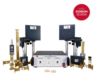
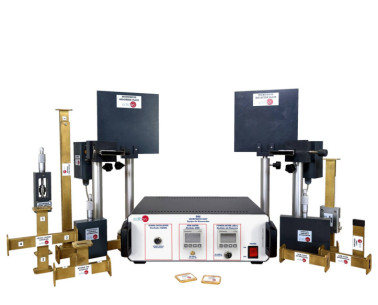
The Antenna Unit, "EAN", is a complete and affordable unit and no extra hardware is required for complete all the practice set.
The "EAN" allows students to learn how to perform the essential antenna measurements: radiation pattern with the measure of the azimuth and elevation plots (electrical and magnetic planes), real time signal level, standing wave ratio (SWR), study the effectiveness of antenna through a wide range of frequencies (bandwidth), directivity and antenna’s power gain.
The "EAN" allows students to learn how to perform the essential antenna measurements: radiation pattern with the measure of the azimuth and elevation plots (electrical and magnetic planes), real time signal level, standing wave ratio (SWR), study the effectiveness of antenna through a wide range of frequencies (bandwidth), directivity and antenna’s power gain. The unit is divided into different blocks of elements:
- RF-Generator and SWR-Meter (in metallic box):
- RF-Generator: It generates a signal whose frequency can be controlled using the potentiometer. The selected frequency (MHz) is displayed on a digital display. The output of this block should be connected to the antenna to be characterized.
- SWR-Meter: It allows to measure the matching quality between the RF-generator and the antenna. In order to simplify the operation with the "EAN" unit, the SWR-Meter is internally connected to the RF-generator and the output. The SWR-meter displays the forward and reflected power and the SWR.
- Transmitter Antenna Tower: It is used to fix the antenna to be characterized. The transmitter tower has two holders to fix the antenna to characterize on horizontal and vertical positions. There is also a degree wheel to adjust the orientation of the antenna.
- Receiver Antenna Tower. It contains the following elements:
- Receiver Tower: It is the place where the receiver antenna should be fixed. The receiver antenna consists of a logarithmic antenna included in the "EAN-1. Antennas Kit 1" suitable for measuring a wide range of frequencies.
- Spectrum Analyzer: It is the instrument that takes measures of the strength of the incoming signal.
- EAN-1. Antennas Kit 1: the "EAN" unit is provided with a set of antennas. The kit includes the most common types of antennas. The antennas are constructed in such a way to allow students to test them in an easy and quick way. The common parts of every antenna are: a fixing system to fix the antenna to the transmitter tower and a SMA connector to connect it to the RF generator.
 Cookie-Präferenzen

