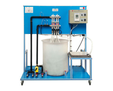
TAAC Gerät für eine Labor-Klimaanlage, computergesteuert (PC)
INNOVATIVE SYSTEME
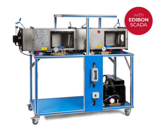
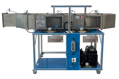
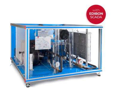
The Computer Controlled Air Conditioning Laboratory Unit, "TAAC", has been designed by EDIBON to study the change of the air conditions and the refrigeration circuit.
Erweiterungen
Laboratorien
ÄHNLICHE NEUIGKEITEN
ALLGEMEINE BESCHREIBUNG
The Computer Controlled Air Conditioning Laboratory Unit, "TAAC", has been designed by EDIBON to study the change of the air conditions and the refrigeration circuit.
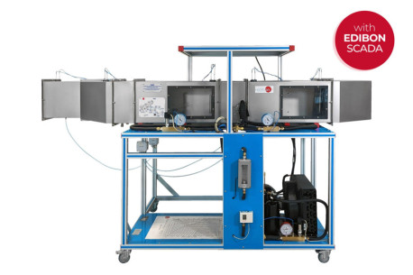
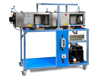
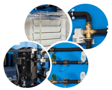
The unit consists of a testing tunnel made of stainless steel, in which there have installed two windows. Inside of the tunnel there is an axial fan (computer controlled) and two heating elements (computer controlled), one situated at the evaporator inlet and other situated at the evaporator outlet.
The unit has a flow sensor and four hygrometers situated along the tunnel. These hygrometers are formed by two temperature sensors (wet and dry bulb).
Two steam lines inject steam from a steam generator (not included) to the tunnel to modify the air characteristics.
The tunnel includes an evaporator in the middle. It consists of a finned radiator through which a coolant flow circulates. This radiator is placed perpendicular to the air flow generated by the fan.
Coolant flows through a closed circuit. It enters to the compressor (computer controlled) and circulates through a filter (to retain particles of condensate), a flow sensor, an expansion valve, the tunnel evaporator (the coolant absorbs the air heat of the flowing through the evaporator) and a condenser.
Several temperature, pressure and flow sensors and manometers have been strategically located, allowing to study the refrigeration cycle and quantify the evaporation and condensation capacity. In addition, the unit includes a high pressure control to avoid an excess of pressure in the unit.
This Computer Controlled Unit is supplied with the EDIBON Computer Control System (SCADA), and includes: The unit itself + a Control Interface Box + a Data Acquisition Board + Computer Control, Data Acquisition and Data Management Software Packages, for controlling the process and all parameters involved in the process.
ÜBUNGEN UND GEFÜHRTE PRAKTIKEN
GEFÜHRTE PRAKTISCHE ÜBUNGEN IM HANDBUCH ENTHALTEN
- Demonstration of the process and components used in heating, cooling, humidification, dehumidification.
- Obtaining the steam generator efficiency curve.
- Energy balance in the steam generator.
- Efficiency determination of preheating element.
- Preheating effect in an air conditioning installation.
- Dehumidification process study.
- Mass balance in the evaporator.
- Energy balance in the evaporator.
- Re-heat effect.
- Experimental determination of the air specific heating capacity.
- Sensors calibration.
MEHR PRAKTISCHE ÜBUNGEN FÜR DAS GERÄT
- Psychrometric chart.
- Usage of psychrometric chart.
- Example of the air properties determination.
- Properties of the refrigerant R513a.
- Enthalpy-Pressure diagram for the refrigerant R513a.
Other possibilities to be done with this Unit:
- Many students view results simultaneously. To view all results in real time in the classroom by means of a projector or an electronic whiteboard.
- Open Control, Multicontrol and Real Time Control. This unit allows intrinsically and/or extrinsically to change the span, gains, proportional, integral, derivative parameters, etc, in real time.
- The Computer Control System with SCADA and PID Control allow a real industrial simulation.
- This unit is totally safe as uses mechanical, electrical and electronic, and software safety devices.
- This unit can be used for doing applied research.
- This unit can be used for giving training courses to Industries even to other Technical Education Institutions.
- Control of the TAAC unit process through the control interface box without the computer.
- Visualization of all the sensors values used in the TAAC unit process.
- By using PLC-PI additional 19 more exercises can be done.
- Several other exercises can be done and designed by the user.
ÄHNLICHE VERFÜGBARE GERÄTE
Gerät für eine Labor-Klimaanlage
Gerät für die Umluft-Klimatisierung
Gerät für Klimaanlage mit Klimakammer und Wasserkühler, computergesteuert (PC)
ERGÄNZENDE AUSRÜSTUNG
Gerät für die Produktion von Warmwasser und Heizsystemen, computergesteuert (PC)
Gerät für den Biomasseprozess, computergesteuert (PC)
Gerät für den Biomasseprozess
Gerät zur Untersuchung der Effizienz eines Heizsystems, computergesteuert (PC)
Trainingsgerät für Warmwasserbereiter
Wärmepumpe für verschiedene Quellen und Wärmetauscher
Fußbodenheizung und/oder Wärmequelle für Wärmepumpe
Luftheizung und/oder Luftwärmetauscher
Gerät für eine Labor-Klimaanlage
Gerät für die Umluft-Klimatisierung, computergesteuert (PC)
Gerät für die Umluft-Klimatisierung
Gerät für die Klimaanlage eines Autos, computergesteuert (PC)
QUALITÄT

KUNDENDIENST

 Cookie-Präferenzen

