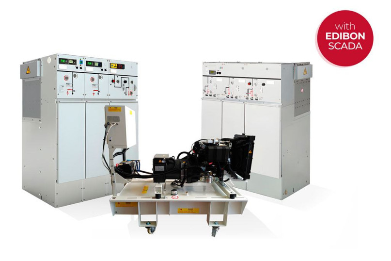
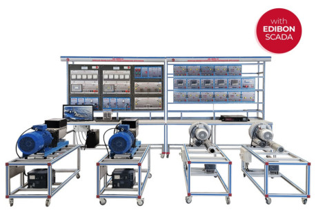
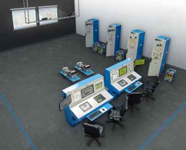
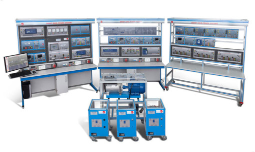
The Computer Controlled Marine Power Generation and Distribution System, "MPGDC", has been designed by EDIBON for both theoretical and practical training in the field of ship power generation and distribution. This system provides several levels of training for the user to acquire real knowledge and experience on the commissioning, operation and the most important maneuvers carried out in marine power generation and distribution systems.
For this purpose, this application includes a specific manual that explains at a theoretical level the topics related to power generation and energy distribution systems on ships. The manual covers topics such as construction, wiring and configuration of the distribution system, power management system, overcurrent protections, configuration of frequency and voltage controllers, tuning of gensets and their controllers, connection and verification of the battery charging system, handling of the switchgear, etc.
The Computer Controlled Marine Power Generation and Distribution System, "MPGDC" is composed of two main subsystems or circuits:
- Low voltage circuit: it consists of 2 diesel generator sets interconnected to the low voltage busbar by means of control and switchgear cubicles through which the rest of the ship’s power system will be serviced. These gensets are equipped with a cooling system like the one used in real ships. It consists of a heat exchanger that operates with salt water and a recirculation pump that sends the coolant to the diesel engines. The necessary maneuvers for the coupling of the generators to the main busbar (see attached diagram for a better understanding) will be carried out through the control and isolation cells, which work at 400 VAC. These generators are controlled by the "Power Management System" (PMS) and will start automatically according to the power demand of the electrical loads. By electrical loads we mean any consumption in the power system, either by the ship’s propulsion electric motors or by the electrical loads that simulate consumption in general, such as the coolant recirculation pump. The uninterruptible power supply system is connected to this same low voltage circuit. This system consists of a high-power LiPeFo battery and a cutting edge bidirectional hybrid inverter. The purpose of this UPS is to keep the battery charged during normal operation of the generator sets and to provide power to the main system in the event of an imminent blackout.
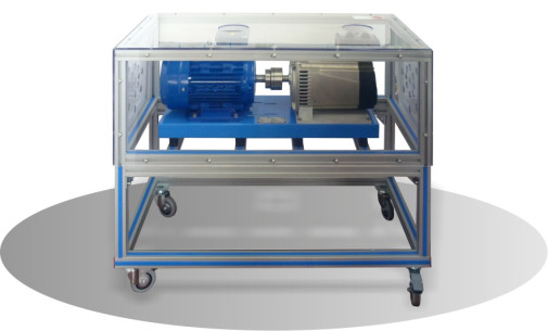
- Medium voltage circuit: this is a subsystem that is fed by the 400 VAC low voltage cells and whose main purpose is to feed two electric drives that will control two high power electric motors. These motors are intended to turn the ship’s propulsion turbines. To simulate the hydraulic load of the turbines, two brakes are coupled to the shaft of the electric motors. Finally, it is worth mentioning that this medium voltage circuit is composed of 12 kV switchgear (actual voltage 400 VAC). The purpose of using these real cells is that the user is trained with real elements that will manipulate tomorrow in real power installations. In this same circuit we can find a step-up transformer which will supply the frequency inverters.
Something interesting to highlight of this didactic unit is that users or professionals can acquire a great knowledge on issues related to the control and management of diesel generator sets used in real ships. Real practices such as the adjustment of their protections, island and parallel operation mode, load sharing or grid connection, can be seen in a real way through this power system.
This unit is focused both for professionals who need training for the commissioning of power systems on ships and for those whose professional focus is more related to the installation of this type of systems.
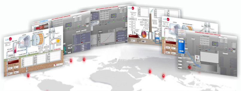
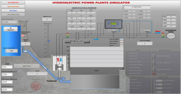
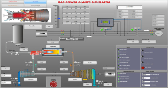
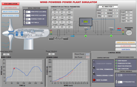
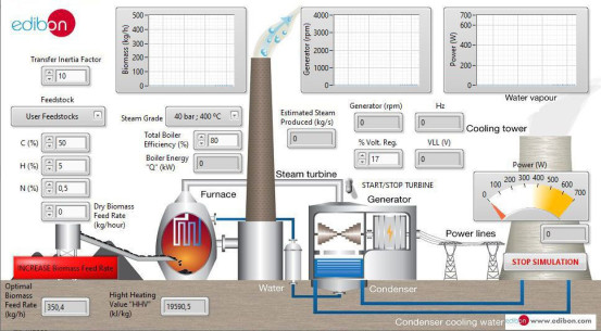
The Computer Controlled Marine Power Generation and Distribution System includes a SCADA data acquisition and control system which faithfully represents a power generation substation with a turbine and generator control center, with network analyzers, circuit breakers, distribution line and resistive and inductive loads. The SCADA is designed to control in real time the entire power system, for example, the speed of the thrusters can be controlled remotely while the user observes the behavior of the system. On the other hand, it is possible to run the two generators in parallel. In this way, the user can understand the importance of optimal power sharing between the two generators. Voltage sags, overspeed, underspeed, overcurrents, overloads and reverse power are some of the many phenomena that the user can study from the SCADA.
On the other hand, from the SCADA itself, it will be possible to create a real situation of failure of the first generator, failure of the second generator, blackout event and finally, restoration of the electrical system thanks to the support of the UPS with hybrid inverter.
This unit is supplied with the EDIBON Computer Control System (SCADA), and includes: The unit itself + Computer Control, Data Acquisition and Data Management Software Packages, for controlling the process and all parameters involved in the process.
 Cookie-Präferenzen

