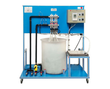
THIBAR44C Wärmepumpe + Klimaanlage + Umkehrkühlung mit 4 Kondensatoren und 4 Verdampfern (Wasser/Luft), computergesteuert

COMPUTER CONTROLLED RERVERSIBLE HEAT PUMP + AIR CONDITIONING  - THIBAR44C

INNOVATIVE SYSTEME

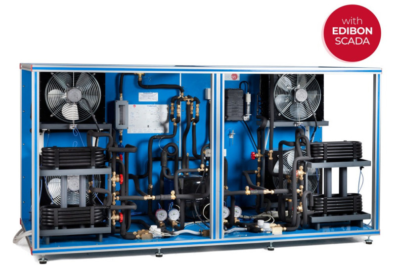
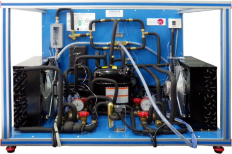
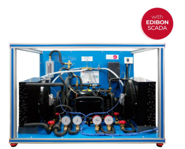
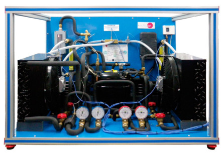
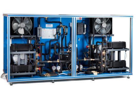
The Computer Controlled Rerversible Heat Pump + Air Conditioning + Refrigeration with 4 Condensers and 4 Evaporators (Water/Air),"THIBAR44C", has as aim introduce the student to the study of the heat pumps, air-conditioning and cooling, as well as to analyze anddetermine the operation typical parameters of the unit depending on the two types of fluids used in the evaporation and condensationprocesses (air and water).

Allgemeine Beschreibung anzeigen

ÄHNLICHE NEUIGKEITEN

ALLGEMEINE BESCHREIBUNG

The Computer Controlled Rerversible Heat Pump + Air Conditioning + Refrigeration with 4 Condensers and 4 Evaporators (Water/Air),"THIBAR44C", has as aim introduce the student to the study of the heat pumps, air-conditioning and cooling, as well as to analyze anddetermine the operation typical parameters of the unit depending on the two types of fluids used in the evaporation and condensationprocesses (air and water).

This unit can have different applications, depending on the type of cold focus or hot focus used in theevaporation and condensation processes.

This unit consists of the following stages:

  • Compression: this stage begins when the coolant enters the compressor. This coolant is compressed, increasing its pressure and temperature. To measure these variables the unit includes a pressure sensor, a manometer and a temperature sensor.
  • Condensation: the coolant has two possibilities, to be diverted towards the air condenser or towards the water condenser. The coolant transfers its heat to the water (or to the air) that flows through the condenser. At the end of this stage, the pressure and temperature of the coolant are measured with a manometer and a temperature sensor.
  • Expansion: the coolant flows through an accumulator and a filter, to retain particles of condensate, and a flow sensor. Then it is directed to the expansion valve, which causes a pressure and temperature drop in the coolant. At the end of this stage the pressure and temperature of the coolant are measured with a manometer and a temperature sensor.
  • Evaporation: the coolant has two possibilities, to be diverted towards the air evaporator or towards the water evaporator. The coolant absorbs the heat of the water (or the air) that flows through the evaporator. At the end of this stage the pressure and temperature of the coolant are measured with a pressure sensor, a manometer and a temperature sensor. Finally, the coolant passes through a liquid separator to retain liquid particles before being directed to the compressor.

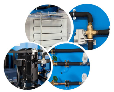
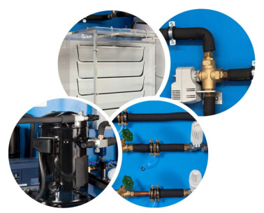
The condensers and evaporators have different sensors to measure the most important parameters (temperatures and flows). In addition, the unit includes a high pressure switch to avoid overpressure in the unit and a four-way valve to change the direction of the coolant.

The four-way valve (or cycle inversion valve) allows to obtain different combinations of Heat Pump, Air Conditioning and Cooling in only one unit.

ÜBUNGEN UND GEFÜHRTE PRAKTIKEN

GEFÜHRTE PRAKTISCHE ÜBUNGEN IM HANDBUCH ENTHALTEN

  1. Determination of the inlet power, generated heat and performance coefficient. Water as heat source. (Water-water heat pump).
  2. Determination of the inlet power, generated heat and performance coefficient. Air as heat source. (Water-air heat pump).
  3. Determination of the inlet power, generated heat and performance coefficient. Air as heat source. (Air-air heat pump).
  4. Determination of the inlet power, generated heat and performance coefficient. Water as heat source. (Air- water heat pump).
  5. Preparation of performance curves of the heat pump with different inlet and outlet temperatures. Water as heat source. (Water-water heat pump).
  6. Preparation of performance curves of the heat pump at different inlet and outlet temperatures. Air as a heat source. (Water-air heat pump).
  7. Preparation of performance curves of the heat pump with different inlet and outlet temperatures. Water as heat source. (Air-water heat pump).
  8. Preparation of the performance curves of the heat pump with different inlet and outlet temperatures. Air as heat source. (Air-air heat pump).
  9. Lay out of the steam compression cycle in a diagram P-H and comparison with the ideal cycle. Water as heat source. (Water-water heat pump).
  10. Lay out of the steam compression cycle in a diagram P-H and comparison with the ideal cycle. Air as heat source. (Water-air heat pump).
  11. Lay out of the steam compression cycle in a diagram P-H and comparison with the ideal cycle. Water as heat source. (Air-water heat pump).
  12. Lay out of the steam compression cycle in a diagram P-H and comparison with the ideal cycle. Air as heat source. (Air-air heat pump).
  13. Preparation of the performance curves of the heat pump based on the properties of the refrigerant and at different condensation and evaporation temperatures. Water as heat source. (Water-water heat pump).
  14. Preparation of the performance curves of the heat pump based on the properties of the refrigerant and at different condensation and evaporation temperatures. Air as heat source. (Water-air heat pump).
  15. Preparation of the performance curves of the heat pump based on the properties of the refrigerant and at different condensation and evaporation temperatures. Water as heat source. (Air-water heat pump).
  16. Preparation of the performance curves of the heat pump based on the properties of the refrigerant and at different condensation and evaporation temperatures. Air as heat source. (Air- air heat pump).
  17. Practices with cycle inversion.
  18. Sensors calibration.

MEHR PRAKTISCHE ÜBUNGEN FÜR DAS GERÄT

  1. Many students view results simultaneously. To view all results in real time in the classroom by means of a projector or an electronic whiteboard.
  2. Open Control, Multicontrol and Real Time Control. This unit allows intrinsically and/or extrinsically to change the span, gains, proportional, integral, derivative parameters, etc, in real time.
  3. The Computer Control System with SCADA and PID Control allow a real industrial simulation.
  4. This unit is totally safe as uses mechanical, electrical and electronic, and software safety devices.
  5. This unit can be used for doing applied research.
  6. This unit can be used for giving training courses to Industries even to other Technical Education Institutions.
  7. Control of the THIBAR44C unit process through the control interface box without the computer.
  8. Visualization of all the sensors values used in the THIBAR44C unit process.
  9. By using PLC-PI additional 19 more exercises can be done.
  10. Several other exercises can be done and designed by the user.

ÄHNLICHE VERFÜGBARE GERÄTE

QUALITÄT

KUNDENDIENST

Informationen anfordern