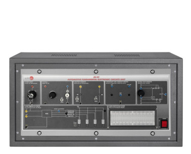
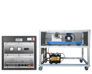
The Automotive Fundamental Electrical Circuits Unit, "AV-ELC", has been designed by EDIBON as a practical and intuitive solution for teaching the most common electrical circuits used in today’s vehicles. Its goal is to provide students with a solid understanding of the behavior of key circuit types, enabling them to identify components, measure signals, locate faults, and understand the logic behind automotive electrical systems.
The "AV-ELC" includes a set of circuits grouped by function: power supply circuits, rectifier circuits, resistor and lamp circuits, capacitor circuits, and logic gate circuits. Each circuit is presented individually and in isolation, which facilitates focused analysis. All test points are clearly labeled and accessible via standard 2 mm lab connectors, making the setup safe and easy to use during practice.
One of the most valuable educational features of this unit is the ability to simulate real faults. Using toggle switches, instructors or students can introduce faults into circuit components, allowing for fault diagnosis practice in a safe, controlled environment. This feature is especially useful for developing troubleshooting skills, which are highly valued in technical and vocational training.
The unit comes with a full set of guided practical exercises, allowing students to progress step by step through each circuit. From identifying components to functional analysis and fault investigation, the "AV-ELC" offers a complete introduction to automotive electrical fundamentals.
 Cookie preferences

 Catalog
 Tender Specifications