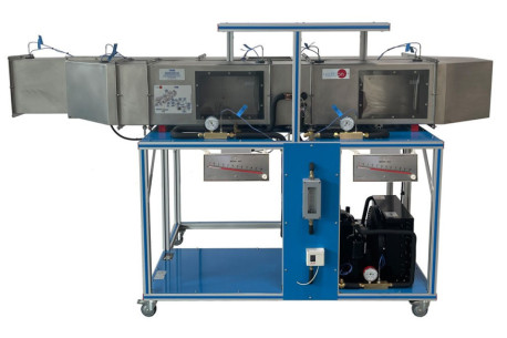
TSCAC Computer Controlled Air Duct Systems Unit
INNOVATIVE SYSTEMS
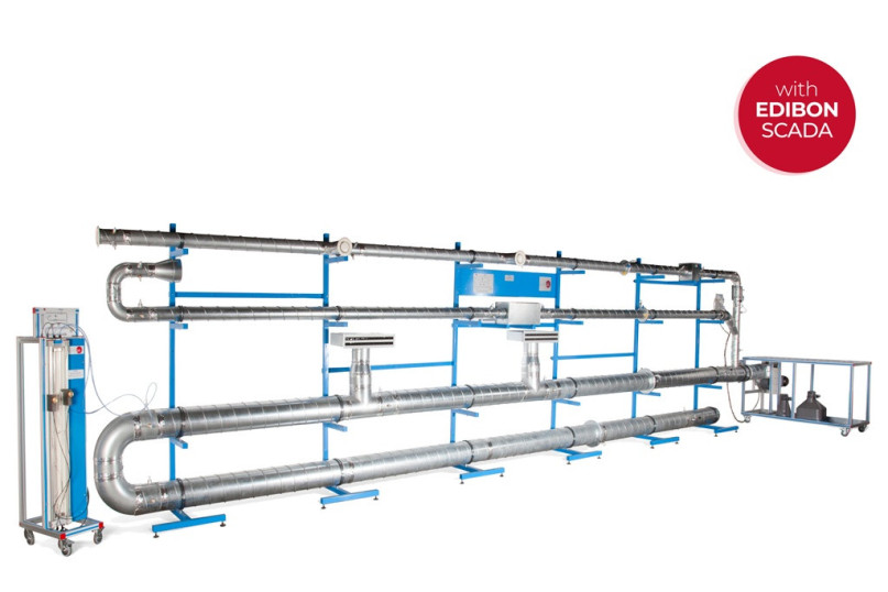
With the Computer Controlled Air Duct Systems Unit, "TSCAC", the user will study the air distribution under different configurations thanks to the supports included with the unit. The user himself will assemble the air ducts using usual elements such as pipes, bends, branches, filters, diffusers and discharge valves.
Expansions
Laboratories
RELATED NEWS
General Description
With the Computer Controlled Air Duct Systems Unit, "TSCAC", the user will study the air distribution under different configurations thanks to the supports included with the unit. The user himself will assemble the air ducts using usual elements such as pipes, bends, branches, filters, diffusers and discharge valves.
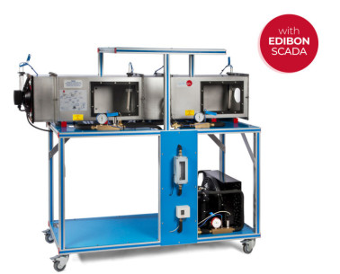
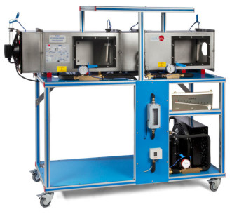
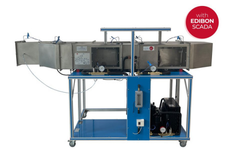
The Computer Controlled Air Duct Systems Unit, "TSCAC", designed by EDIBON, consists of a set of metal ventilation ducts of different diameter, which allow for composing different ventilation networks to distribute air thanks to a series of movable and adjustable supports with the objective of understanding and handling the most important aspects related to them.
The user can build the ventilation system using usual components, such as tubes, bends, branches, filters, discharge valves, etc. After making the assembly, the effect of individual components on the pressure drop and, therefore, on the flowing air velocity and flow will be studied. Thanks to the arrangement of six pressure sensors, the volumetric flow of air in each line of the system can be determined in real time.
The duct system is supplied by a computer controlled variable flow fan, whose absorbed power will be required to determine its characteristic curve, as well as the operation point of the whole system.
The path followed by the air along the different elements included in the system will be chosen by using butterfly valves, diaphragm valves and distribution elements. The air, when flowing through the elements mentioned, will suffer pressure drops that will be quantified due to the arrangement of several exchangeable connections, where the static and total pressure can be measured thanks to the location of Pitot tubes in every connection.
There is a quick connection portable differential "U" manometer to determine those pressures. It allows for knowing the differential pressure between whatever points of the system. Besides, there is a portable anemometer to measure velocities and flows at the outlet of the ducts.
This Computer Controlled Unit is supplied with the EDIBON Computer Control System (SCADA), and includes: The unit itself + a Control Interface Box + a Data Acquisition Board + Computer Control, Data Acquisition and Data Management Software Packages, for controlling the process and all parameters involved in the process.
Exercises and guided practices
GUIDED PRACTICAL EXERCISES INCLUDED IN THE MANUAL
- Understanding, assembling and operating air systems and their main elements.
- Determining the dynamic pressure using several methods.
- Determining the flow velocity using several methods.
- Determining the volumetric flow using several methods.
- Determining the pressure drop in air systems components ducts, bends, valves, filters, etc.
- Characteristic curve of static pressure of the fan.
- Determining the efficiency of the fan.
- Characteristic curve and operation point in individual lines of the system.
- Air distribution in ventilation ducts systems.
- Characteristic curve and operation point in a complete ventilation duct system.
- Sensors calibration.
MORE PRACTICAL EXERCISES TO BE DONE WITH THE UNIT
- Many students view results simultaneously. To view all results in real time in the classroom by means of a projector or an electronic whiteboard.
- Open Control, Multicontrol and Real Time Control. This unit allows intrinsically and/or extrinsically to change the span, gains, proportional, integral, derivative parameters, etc, in real time.
- The Computer Control System with SCADA and PID Control allow a real industrial simulation.
- This unit is totally safe as uses mechanical, electrical and electronic, and software safety devices.
- This unit can be used for doing applied research.
- This unit can be used for giving training courses to Industries even to other Technical Education Institutions.
- Control of the TSCAC unit process through the control interface box without the computer.
- Visualization of all the sensors values used in the TSCAC unit process.
- By using PLC-PI additional 19 more exercises can be done.
- Several other exercises can be done and designed by the user.
SUPPLEMENTARY EQUIPMENT
Computer Controlled Biomass Process Unit
Biomass Process Unit
Computer Controlled Unit to Study the Efficiency of a Heating System
Water Heaters Training Unit
Heat Pump for different Heat Sources and Heat Exchangers
Underfloor Heating and/or Heat Source for Heat Pump
Fan Heater and/or Air Heat Exchanger
Computer Controlled Air Conditioning Laboratory Unit
Air Conditioning Laboratory Unit
Computer Controlled Recirculating Air Conditioning Unit
Recirculating Air Conditioning Unit
Quality

AFTER-SALES SERVICE

 Cookie preferences

