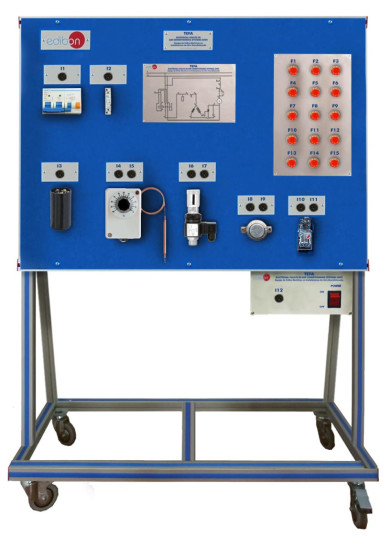
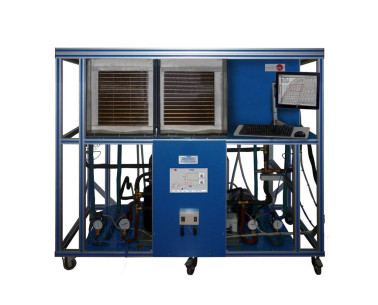
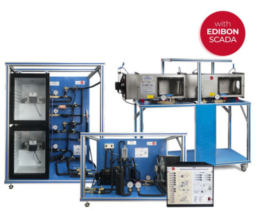
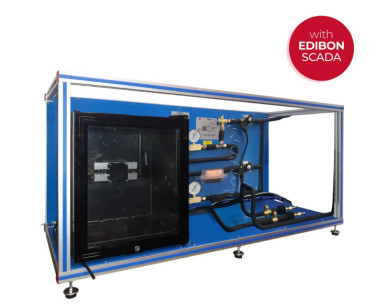
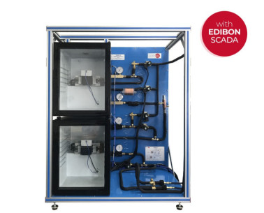
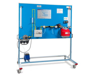
The Electrical Faults in Air Conditioning Systems Unit,"TEFA", is designed in a simple way in order to transmit comprehensible knowledge about how identify electrical faults in air conditioning systems. For this purpose, concepts are included to provide experience in the design and operation of the individual electrical components and reading circuit diagrams.
This unit is clearly designed to give the students the most realistic knowledge of air conditioning systems demonstrating how electrical circuits of these systems work. The air conditioning system mainly consists of a refrigerant compressor and fan at the air cooler. This part of the system is simulated (compressor and fan) and the "TEFA" unit is focused in the control circuits of air conditioning systems. The unit includes a thermostat to switch on/off the compressor. On the other hand, via ballast, the fan motor speed can be switched in two stages. In addition, the unit includes a star-up relay and a star-up capacitor to control the start of the motor compressor. Besides, the unit includes protection devices similarly to the air conditioning systems such as circuit breakers and overheat protection to complete the air conditioning electrical circuit.
All the components are connected on terminal blocks and they are arranged on a front panel such that they are all accessible and very visible. In addition, through the cables and electrical elements included in this unit it is possible to set-up many circuits correctly and operationally and this allow simulate 16 different typical faults in air conditioning systems.
One important thing is that the state of the simulated components such as compressor and fan is indicated via lamps in the circuit diagram of the unit´s front panel.
The unit´s front panel includes jack connections in order to check with the included multimeter voltages and resistances for faults detection such as coil fracture in the motor or faulty switching contact.
The unit´s front panel clearly depicts the real circuit diagram to facilitate the allocation of the measurement points.
The following are the most important objectives and experiments which can be carried out with this unit:
- Electrical design and principle of operation of air conditioning systems.
- Read and understand electrical circuit diagrams.
- Fault finding in electrical components in idle state and under mains voltage.
- Design and operation of electrical components in an air conditioning system: Start-up capacitor, Start-up relay, Overheat protection, Main contactor, Automatic fuse, On/off switch, Speed switch and Thermostat.
 Cookie preferences

