FME29 Kaplan Turbine
INNOVATIVE SYSTEMS
With the Kaplan Turbine unit, "FME29", designed by EDIBON, we study the Kaplan turbines commonly used when we have high flow rates but low flow height.
Expansions
Laboratories
RELATED NEWS
General Description
With the Kaplan Turbine unit, "FME29", designed by EDIBON, we study the Kaplan turbines commonly used when we have high flow rates but low flow height.
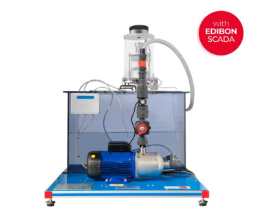
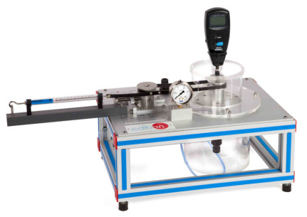
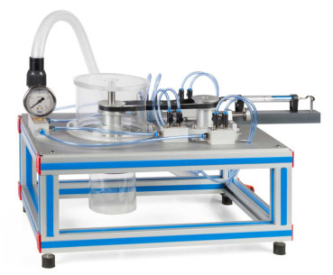
This unit consists on a miniature Kaplan turbine. The water inlet flow is controlled by a valve situated in the Hydraulic Bench (FME00) or Basic Hydraulic Feed System (FME00/B).
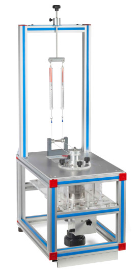
It includes a distributor with adjustable guide vanes that allow for control of the water flow in the turbine. It has a braking system, connected to two dynamometers, that allows to vary the load supplied to the turbine. The feed or spiral chamber is provided with a damping cover and two tubes to avoid water overflow its name indicates that it is spiral-shaped and for this reason it is known as snail chamber. Thanks to its design, the water flows at a constant velocity without forming swirls this way, there are no load losses.
It is also provided with a draft tube that consists of a connection that joins the turbine with the outlet channel its objective is to recover the maximum amount of water kinetic energy when it gets out of the turbine. The inlet pressure of the turbine is measured with a U-manometer situated at the turbine inlet. The turbine’s axis velocity is determined by a tachometer.
Exercises and guided practices
GUIDED PRACTICAL EXERCISES INCLUDED IN THE MANUAL
- Determination of the operative characteristics of Kaplan Turbine at different velocities.
- Flow calculation.
- Determination of the operation mechanical curves.
- Determination of the operation hydraulic curves.
- Adimensional analysis.
SIMILAR UNITS AVAILABLE
SUPPLEMENTARY EQUIPMENT
Basic Fluids Mechanics Integrated Laboratory
Pelton Turbine
Radial Flow Turbine
Axial Flow Turbine
Francis Turbine
Data Acquisition System and Sensors
Quality

AFTER-SALES SERVICE

 Cookie preferences

