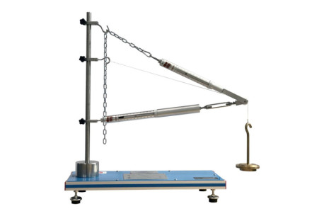
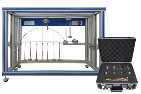
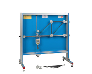
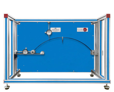
The Suspension Bridge Unit, "MVS", has been meticulously designed by EDIBON to explore the dynamics of stresses in a suspension bridge system. This unit simulates a suspension bridge using a deck and two parallel main cables, allowing students to study the tensions in the main cables.
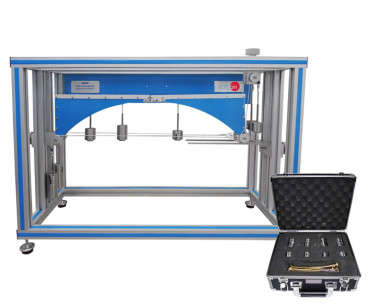
The bridge deck is simulated by a lightweight alloy beam, which is supported by the two parallel main cables through bars that act as suspenders. These suspenders are distributed at constant and relatively short distances, supporting the loads applied to the beam. Loads are applied to the beam by placing masses at a series of load points, simulating a distributed load.
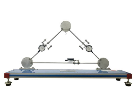
The tensions generated in the suspenders are transmitted to the main cables and then to the pulleys, where they are counteracted by appropriately placed masses. The suspended beam acts as the bridge deck, supported by the main cables through vertical suspenders. The main cables support the tension created by the loads, transmitting it to the pulleys for counteraction. Additionally, the system includes a set of weights and cords to apply and adjust the loads in the system.
The Suspension Bridge Unit, "MVS", ultimately facilitates the understanding of the principles of suspension bridges, allowing practical exercises to compare theoretical and experimental tensions in the cables and study how the bridge suspension responds to different load conditions. This unit comes with a set of weights to facilitate the performance of all experiments.
 Cookie preferences

 Catalog
 Tender Specifications