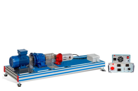
EEE Wind Energy Unit

WIND ENERGY UNIT - EEE

INNOVATIVE SYSTEMS

The Wind Energy Unit, "EEE", contains an aerogenerator, in laboratory-scale, and is used to study the conversion of kinetic wind energy into electrical energy and to study the influence of some factors on this generation.

See general description

RELATED NEWS

General Description

The Wind Energy Unit, "EEE", contains an aerogenerator, in laboratory-scale, and is used to study the conversion of kinetic wind energy into electrical energy and to study the influence of some factors on this generation.

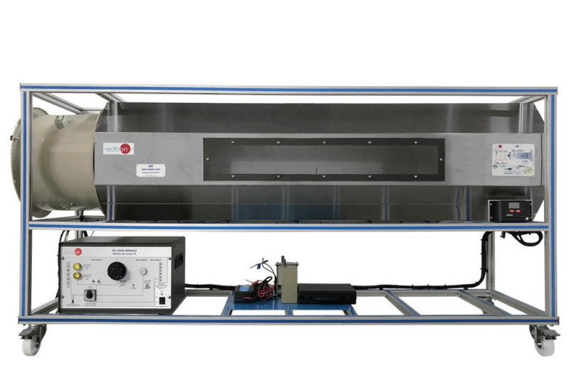
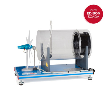
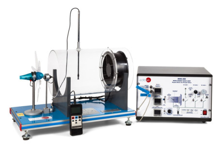
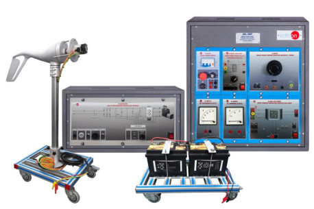
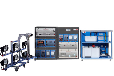
The unit consists of a stainless steel tunnel, an aerogenerator and an axial fan with variable speed. A rotor (or turbine) to place up to blades and a generator are the core elements of the aerogenerator.

The air speed is varied by changing the rotational speed of the axial fan. This fan generates the air flow required to set the rotor of the wind energy unit. The generator converts the rotor's kinetic energy into electrical energy.

The aerogenerator incidence angle and the angle of every blade can be modified. The blades can be removable and it's possible to set different blade configurations.

This unit includes a DC Load Regulator, an auxiliary battery charger, a battery and a DC Loads module. The DC Loads module contains DC lamps, rheostat, DC motor, load selector and switches to select the type of load:

  • Position 1: The aerogenerator or regulator operates at open circuit voltage.
  • Position 2: The DC lamps and the rheostat are directly connected to the aerogenerator or regulator. These loads can be connected independently or in parallel with the help of manual switches.
  • Position 3: The DC motor is directly connected to the aerogenerator or regulator.
  • Position 4: Bypass mode, there are no DC loads.

The following parameters are measured: air temperature, air speed, speed of the rotor and voltage and current. There is a temperature sensor before the rotor of the aerogenerator. The air speed is measured with an anemometer placed in the tunnel and also is determined the rotational speed of the aerogenerator (r.p.m.). A voltage and current sensor allows to measure the voltage and current to determine the power.

It is possible to know, in real time, the value of the DC voltage and the current given by aerogenerator, measured before and after the regulator.

Exercises and guided practices

GUIDED PRACTICAL EXERCISES INCLUDED IN THE MANUAL

  1. Identification and familiarization with all components of the unit and how they are associated with its operation.
  2. Familiarization with the regulator parameters and the wind energy measurements.
  3. Study of the conversion of kinetic wind energy into electrical energy.
  4. Study of the power generated by the aerogenerator depending on the wind speed.
  5. Determination of the typical parameters of the aerogenerator (short circuit current, open-circuit voltage, maximum power).
  6. Determination of the I-V curve.
  7. Study of voltage, current and power in function of different loads.
  8. Study of the influence of the load variation on the aerogenerator.
  9. Determination of the maximum power output of the aerogenerator.
  10. Determination of the P-air speed curve.
  11. Study of the power generated by the aerogenerator depending on the incident angle of the air.
  12. Study of the characteristic curve of the rotor.
  13. Study of the connection of loads to direct voltage.

MORE PRACTICAL EXERCISES TO BE DONE WITH THE UNIT

  1. Study of the power coefficient.
  2. Study of the aerogenerator operation in function of the blade configuration (aerogenerator with six, three or two blades).
  3. Study of the optimum number of blades.
  4. Study of the aerogenerator operation in function of the angle of the blades.
  5. Study of the efficiency of a wind power unit.
  6. Determination of the efficiency of a wind power unit in function of the number of blades, angle of the blades and angle of the generator.

Practices to be done with the recommended element "EE-KIT":

  1. Study of the connection of loads to alternating voltage of 220 V.

Practices to be done with the additional recommended element "EE-HYB-KIT":

  1. Study of the hybrid inverter’s grid connection procedure: correct sequence of battery and grid switches.
  2. Study of the hybrid inverter configuration.
  3. Study of the hybrid inverter in grid connection mode.
  4. Study of the hybrid inverter in island mode.
  5. Study of the behavior of the hybrid inverter in the event of a blackout.
  6. Study of the charging process of the battery from the laboratory grid through the hybrid inverter.
  7. Study of the battery charging process from a renewable energy source.
  8. Study of the power flows of the battery and the grid under variations of the energy demand with the variable resistive load.
  9. Study of the response of the hybrid inverter when the critical discharge point of the battery is reached.
  10. Study of the energy balance between the battery-charge-grid by means of the analog ammeters and voltmeters incorporated in the kit.

Practices to be done with the additional recommended element "EEE/T":

  1. Determination and study of the thrust force on the wind turbine.
  2. Determination and study of the mechanical torque of the wind turbine.
View more

SIMILAR UNITS AVAILABLE

Quality

AFTER-SALES SERVICE

Ask for information