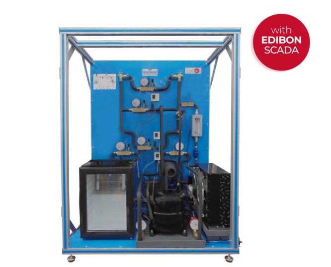
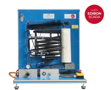
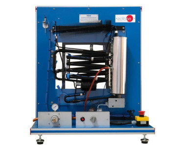
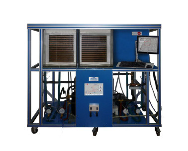
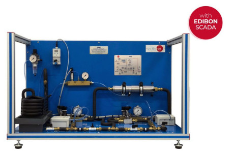
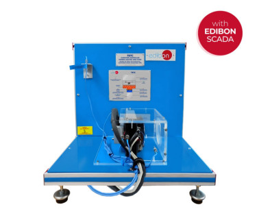
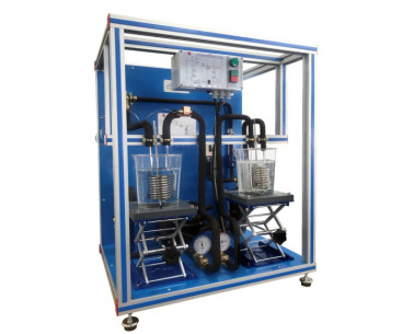
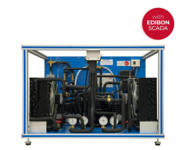
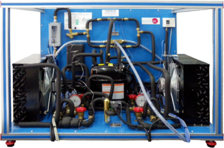
The Computer Controlled Two-Stage Compression Refrigeration Unit, "TSCC", is clearly organized and represents a two-stage compression refrigeration system to obtain low temperatures.
The main components of the unit are:
- Two hermetic compressors in series.
- Condenser with fan.
- Expansion valve.
- Evaporator with fan.
The low pressure saturated refrigerant vapor, coming from the evaporator, is compressed in two compressors in series, increasing the temperature and transforming the saturated steam refrigerant into superheated steam refrigerant.
The high pressure superheated steam coming from the second compressor flows inside an air condenser where the refrigerant, in the vapor phase, transfers heat to the atmospheric air (hot source) as it passes through the tubes, producing a change of state of the refrigerant to liquid through a condensation process. The refrigerant liquid at the condenser outlet goes to an expansion valve, whose function is to control the flow of refrigerant in liquid state entering the evaporator.
Before the expansion process, the refrigerant can optionally go through a heat exchanger by valves, where it is possible to increase the subcooling of the liquid refrigerant.
The low-pressure liquid refrigerant coming from the expansion valve is introduced into an evaporator, producing a heat transfer from the cold source (atmospheric air) to the refrigerant and a phase change of the refrigerant, which becomes saturated steam. This process is isobaric (P=constant). The evaporator is located inside a refrigeration chamber, which includes an adjustable power heating element to simulate a variation in the conditions of the system and create different thermal loads.
At the end of this stage the cycle is closed and the refrigerant flow enters both compressors in series again. Between both compression stages, it is optional to make the refrigerant pass through an intermediate refrigeration stage by injecting the liquid refrigerant coming from the condenser and storage tank to the low pressure compressor outlet. This liquid refrigerant injected cools the refrigerant that enters the high pressure compressor.
The circuit also includes temperature and pressure measuring devices at key points of the cycle, a filter, a refrigerant storage tank to ensure an adequate flow of refrigerant in the circuit and a liquid separator to prevent liquid from entering the compressor.
This Computer Controlled Unit is supplied with the EDIBON Computer Control System (SCADA), and includes: The unit itself + a Control Interface Box + a Data Acquisition Board + Computer Control, Data Acquisition and Data Management Software Packages, for controlling the process and all parameters involved in the process.
 Préférences sur les cookies

