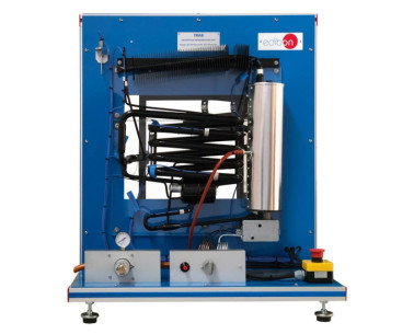
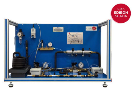
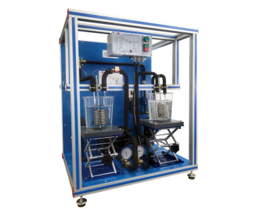
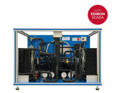
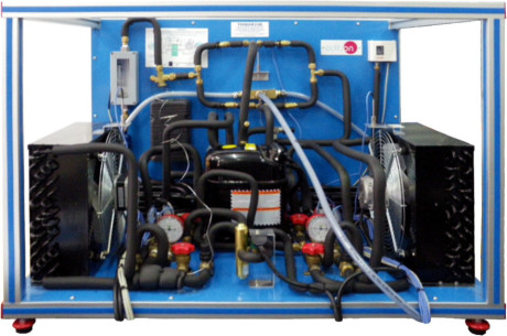
TRCVC Unité de Réfrigération par Compression de Vapeur, Contrôlée par Ordinateur (PC)
SYSTEMES INNOVANTS
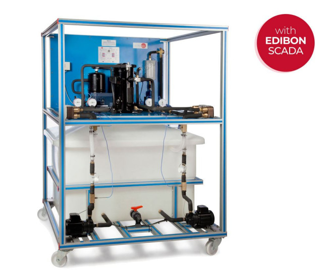
The Computer Controlled Vapour-Compression Refrigeration Unit, "TRCVC", allows the understanding of the vapor-compression refrigeration process by changing the operation of the different parts of the process, and to study the response of the system.
Expansions
Laboratories
NOUVELLES LIÉES
Description Générale
The Computer Controlled Vapour-Compression Refrigeration Unit, "TRCVC", allows the understanding of the vapor-compression refrigeration process by changing the operation of the different parts of the process, and to study the response of the system.
This unit consists of the following stages:
- Compression: This stage begins when the coolant enters to the computer controlled compressor. This coolant is compressed, increasing its pressure and temperature. To measure these variables the unit includes a pressure sensor, a manometer and a temperature sensor.
- Condensation: The coolant circulates through the condenser. The coolant transfers its heat to the water that flows through the condenser. At the end of this stage, the pressure and the temperature of the coolant are measured by means of a manometer and a temperature sensor.
- Expansion: The coolant circulates through an accumulator of condensate and a filter, to retain particles of condensate, and a flow sensor. Next it circulates through the expansion valve, which causes a pressure drop and temperature of the coolant. At the end of this stage, the pressure and the temperature of the coolant are measured by means of a manometer and temperature sensors.
- Evaporation: The coolant circulates through the evaporator. The coolant absorbs the heat of the water that flows through the evaporator. At the end of this stage, the pressure and the temperature of the coolant are measured by means of a pressure sensor, a manometer and a temperature sensor. Finally, the coolant circulates through a liquid separator to retain liquid particles before going on to the compressor.
Two computer controlled pumps impel water from a water reservoir to the condenser and the evaporator. The inlet water temperatures, the outlet water temperatures and the water flows are measured by means of flow sensors and temperature sensors.
In addition, the unit includes a high pressure control to avoid an excess of pressure in the unit.
This Computer Controlled Unit is supplied with the EDIBON Computer Control System (SCADA), and includes: The unit itself + a Control Interface Box + a Data Acquisition Board + Computer Control, Data Acquisition and Data Management Software Packages, for controlling the process and all parameters involved in the process.
Des exercices et pratiques guidées
EXERCICES GUIDÉS INCLUS DANS LE MANUEL
- Demonstration of the features, characteristics and operation of a vapour compression refrigeration system, involving the combined processes of compression, condensation, expansion and evaporation.
- Determination of the inlet power, produced heat and coefficient of performance (COP).
- Preparation of performance curves of the heat pump with different inlet and outlet temperatures.
- Lay out of the vapour compression cycle in a P-h diagram and comparison with the ideal cycle.
- Preparation of the performance curves of the heat pump based on the properties of the coolant at different condensation and evaporation temperatures6.- Investigation of the compressor speed effect (coolant flow rate) on the coefficient of performance (COP).
- Sensors calibration.
PLUS D'EXERCICES PRATIQUES À EFFECTUER AVEC CETTE ÉQUIPEMENT
- Properties of the refrigerant R-513a.
- Enthalpy-Pressure diagram for the refrigerant R-513a.
- Energy balance.
- Study the relation between pressure and temperature.
- Modelling the system thermodynamically by plotting P-h and T-s diagrams using the properties for R-513a.
- Analysis of the pressure relation effect in the system behavior.
Other possibilities to be done with this Unit:
- Many students view results simultaneously. To view all results in real time in the classroom by means of a projector or an electronic whiteboard.
- Open Control, Multicontrol and Real Time Control. This unit allows intrinsically and/or extrinsically to change the span, gains, proportional, integral, derivative parameters, etc, in real time.
- The Computer Control System with SCADA allows a real industrial simulation.
- This unit is totally safe as uses mechanical, electrical/electronic, and software safety devices.
- This unit can be used for doing applied research.
- This unit can be used for giving training courses to Industries even to other Technical Education Institutions.
- Control of the TRCVC unit process through the control interface box without the computer.
- Visualization of all the sensors values used in the TRCVC unit process.
- By using PLC-PI additional 19 more exercises can be done.
- Several other exercises can be done and designed by the user.
EQUIPEMENT COMPLEMENTAIRE
Tour de Refroidissement de bureau
Unité de Démonstration du Cycle de Réfrigération, Contrôlée par Ordinateur (PC)
Unité de Démonstration du Cycle de Réfrigération
Unité de Réfrigération par Absorption, Contrôlée par Ordinateur (PC)
Unité de réfrigération par absorption
Unité de Régulation de la Puissance et des Défauts dans les Installations de Réfrigération, Contrôlée par Ordinateur (PC)
Unité de Réfrigerateur Vortex, Contrôlée par Ordinateur (PC)
Pompe à Chaleur Thermoélectrique, Contrôlé par Ordinateur (PC)
Unité de Circuit de Réfrigération par Compression
Réversible Pompe à Chaleur + Climatisation + Réfrigération avec 2 condenseurs et 2 évaporateurs (d'eau/ d'air), Contrôlé par Ordinateur (PC)
Réversible Pompe à Chaleur + Climatisation + Réfrigération avec 2 condenseurs et 2 évaporateur (d'eau/d'air)
Qualité

Service après vente

 Préférences sur les cookies

