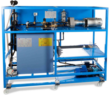
TTVC Turbin Uap, Dikendalikan dari Komputer (PC)
SISTEM INOVATIF
The Computer Controlled Steam Turbine, "TTVC", allows to study, in conjunction with a steam generator, a steam power plant.
Ekspansi
Laboratorium
BERITA TERKAIT
GAMBARAN UMUM
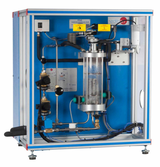
The Computer Controlled Steam Turbine, "TTVC", consists of a single stage impulse steam turbine. It includes an injector, a brake, a water cooled condenser, safety mechanisms and all the necessary controls and instrumentation.
The steam passes through two computer controlled and mounted in series solenoid valves before entering the injector.
The steam passes through the injector with an angle of incidence of 20 º towards the blades of the turbine, generating work on them and making the turbine rotate. According to the steam energy, there will be more or less energy in the turbine.
After passing through the turbine, the steam expands and, is collected into the condenser. The steam is condensed by a coil through which cold water circulates.
The turbine is loaded using a brake, which rotates joined to the turbine shaft, to measure the torque. The brake runs against a belt, which is tensioned by a manual screw to vary the torque.
There is a solenoid valve at the outlet of the condenser. When this valve is closed it allows, together with a level sensor, to condense a known volume at a specific time. Thus, the steam flow is determined.
Pressures, temperatures, refrigeration water flow and speed of the turbine shaft are measured using sensors, the force of the brake is measured by a force sensor (load cell) and the steam flow.
The instrumentation allows the torque of the brake to be measured, together with the mechanical power, steam mass flow and steam consumption of the unit.
The unit is equipped with safety devices: a pressure switch and a safety valve for the condenser and PMMA protection screens.
Steam generator is required to work with the TTVC unit. It must have a steam production of 8 Kg/h at minimum pressures of 6 bar. EDIBON can offer its Steam Generator (TGV-6KWA), suitable to work with this unit.
This Computer Controlled Unit is supplied with the EDIBON Computer Control System (SCADA), and includes: The unit itself + a Control Interface Box + a Data Acquisition Board + Computer Control, Data Acquisition and Data Management Software Packages, for controlling the process and all parameters involved in the process.
LATIHAN DAN PRAKTEK PEDOMAN
LATIHAN PRAKTIS YANG DIANDAL TERMASUK DALAM PANDUAN
- Identification and familiarization with all components of the unit.
- Study and familiarization with turbines.
- Flow calculation.
- Determination of the torsion torque, power and specific consumption of steam when operating at constant inlet pressure but variable outlet pressures.
- Determination of the torsion torque, power and specific consumption of steam when operating at constant outletpressure but variable inlet pressures.
- Determination of friction losses in the turbine.
- Determination of the efficiency of the turbine.
- Determination of the heat-power ratio at several outlet pressures.
LEBIH BANYAK LATIHAN PRAKTIS YANG AKAN DILAKUKAN DENGAN UNIT
- Sensors calibration.
- Study of the operation curves for the turbines.
- Study of the Rankine Cycle.
- Representation of the time evolution of the angular speed.
- Determination of the angular deceleration.
- Representation of the angular deceleration, friction torque and friction power versus angular speed.
- Representation of the torsion torque, shaft power and steam consumption versus angular speed (for different outlet pressure).
- Representation of the mass flow versus condenser pressure (for different outlet pressure).
- Representation of the torsion torque, shaft power and steam consumption versus angular speed (for different inlet pressure).
- Representation of the mass flow versus condenser pressure (for different inlet pressure).
- Determination of isentropic efficiency.
- Determination of thermal efficiency.
Other possibilities to be done with this Unit:
- Many students view results simultaneously. To view all results in real time in the classroom by means of a projector or an electronic whiteboard.
- Open Control, Multicontrol and Real Time Control. This unit allows intrinsically and/or extrinsically to change the span, gains, proportional, integral, derivative parameters, etc, in real time.
- The Computer Control System with SCADA and PID Control allow a real industrial simulation.
- This unit is totally safe as uses mechanical, electrical and electronic, and software safety devices.
- This unit can be used for doing applied research.
- This unit can be used for giving training courses to Industries even to other Technical Education Institutions.
- Control of the TTVC unit process through the control interface box without the computer.
- Visualization of all the sensors values used in the TTVC unit process.
- By using PLC-PI additional 19 more exercises can be done.
- Several other exercises can be done and designed by the user.
PERALATAN KOMPLEMENTER
Pembangkit Listrik Tenaga Uap hingga 20 kW, Dikendalikan dari Komputer (PC) dan Layar Sentuh
Turbin Uap dengan Sumber Energi Surya, Dikendalikan dari Komputer (PC)
Peralatan Siklus Organik Rankine, Dikendalikan dari Komputer (PC)
KUALITAS

LAYANAN PURNA JUAL

 Preferensi cookie

