Logic gates and the circuits created with them constitute combinational logic, so called because the output only depends on the combination of the input variables present.
There is a second group of logic circuits called sequential logic, so called because the output depends, in addition to the input variables, on the value previously present at the output. This means that these circuits are equipped with memory. In addition, a large proportion of sequential circuits are only activated by a cyclic or clock signal and are called synchronous sequential circuits.
The edge trigger time can last for the duration of the clock signal (pulse trigger) or the instant of change from 0 to 1 (edge trigger).
In the elements activated by edge, a small triangle is drawn on the clock connection, which is completed with a circle to specify that the edge is falling (this is the most frequent activation).
For the study of sequential circuits, use is made of the chronogram, the graphic representation of how both the inputs and the output of the circuit evolve over time:
Basic sequential circuits are called bistables, scales or flip-flops.
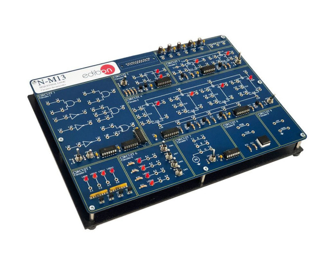
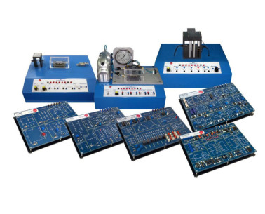
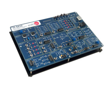
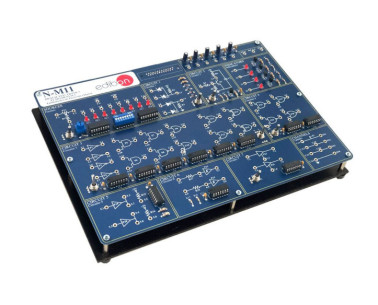
With Basic Sequential Circuits Module, "N-M13", designed by EDIBON, all types of bistables, counters, flip-flops, synchronous sequential circuits and the operation of memories can be studied.
In addition, faults can be simulated in most of the circuits under study. The student must investigate what is happening in the circuit and why it is not working properly. These faults simulations can be of several types from damage components to a hypothetical incorrect circuit assembly.
 クッキーの設定

