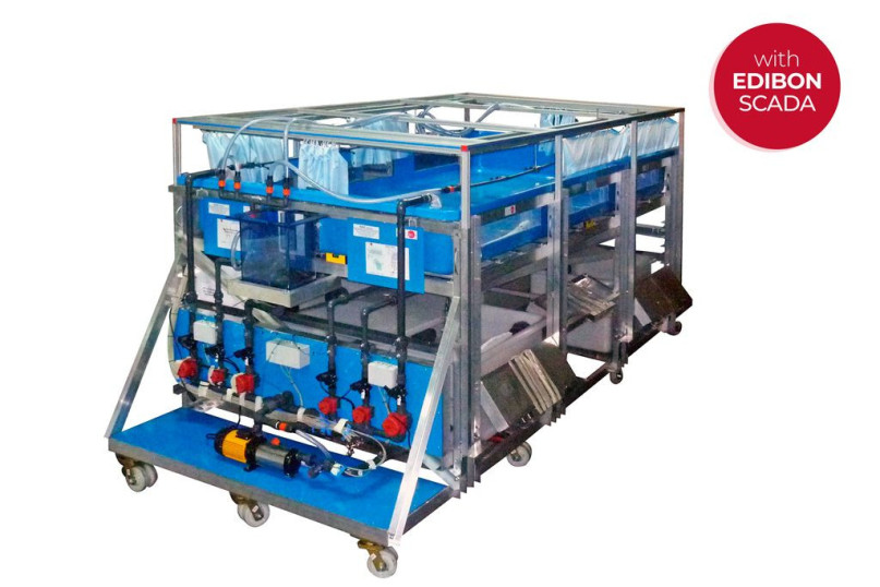
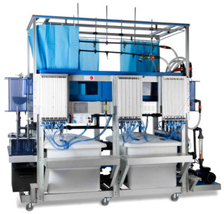
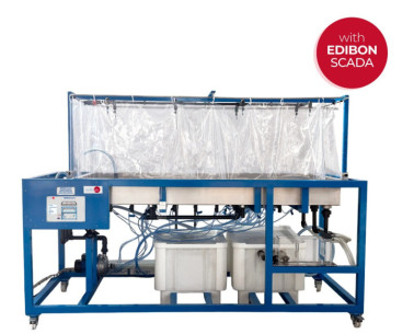
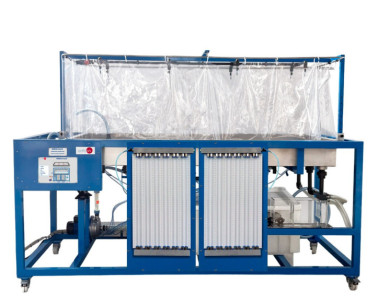
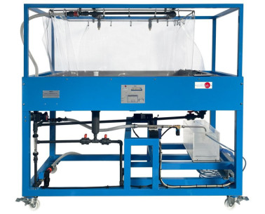
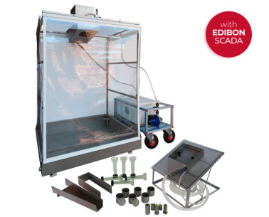
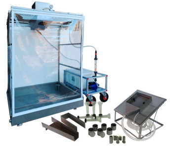
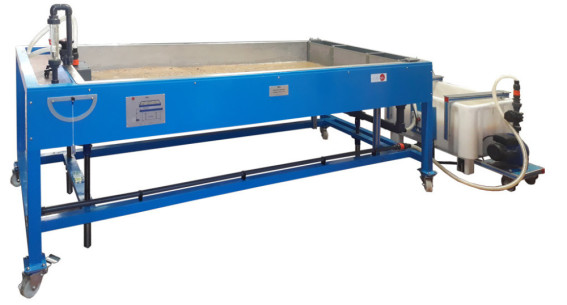
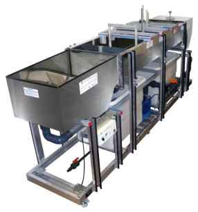
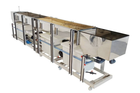
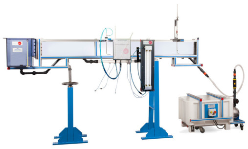
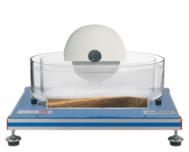
The main element of the unit is a test tank, which can be filled with sand. Water is supplied to the test tank through different systems: from two flexible separate hoses (simulating water inlets), from an inlet tank (simulating a river), from spray and showers nozzles located above the tank (simulating rain), or from French sources/drains. Water is output from a river outlet tank, from the drainages located on two test tank corners, from the french sources/drains, which have independent outlets or from the overflows. Four large plastic storage tanks are located under the test tank to store water. A computer controlled pump with speed regulation impels water from the storage tanks to the test tank.
Two flexible separate hoses, placed at the test tank front side, allow to add great inlet flows.
In order to be able to simulate a river, the test tank has a tank attached to the inlet and other tank attached to the outlet. Gravel can be put inside the river inlet tank to deaden the flow and avoid turbulence. The use of a suitable channel section provides appropriate flow conditions in the test tank. The river outlet tank is located at the other end of the test tank and is used for hydrographs, run-off and river formation demonstrations.
The river tanks are communicated with the test tank through a floodgate that has two trap doors, a hermetic one and a meshed one.
Eight spray nozzles are mounted at a double line mobile bridge placed on the test tank and are arranged in a longitudinally equidistant way to provide an even water distribution along the test tank. These nozzles are also adjustable in height and width and can be easily fixed. Each nozzle has an associated ball valve, allowing a wide variety of moving rain precipitation patterns to be simulated.
Two shower nozzles with multiple flows are placed on the test tank and allow storms and local inputs simulation. These nozzles are also adjustable in height and length and they can be separated from the support to move them manually.
The subsurface flow inputs are via two french sources/drains, located in the middle of the test tank. These french sources/drains extend the full width of the tank. Each french source/drain can be configured as an inlet or an outlet to permit a wide variety of hydrological demonstrations.
The outlet tank consists of a sediment collection basket. So, it is possible to measure with a sensor the quantity of collected sediment over a period of time.
There are three tanks at the rear part of the unit, each of them connected to one french source/drain and the other one connected to the drainages. Each one of these tanks has a spillway, which allows to calculate the outlet flow of each tank. The water flow in each tank is measured by a sensor. The outlet system (from french sources/drains or drainages to tanks) includes three diaphragm valves to regulate the flow and each line includes a solenoid valve.
The test tank includes two overflows that are communicated with the storage tanks.
The water table can be kept constant by means of these overflows, with adjustable height.
The flow of all the inlet systems can be regulated by a group of diaphragm valves located at the front side of the unit. There are six orifice plates that allow to measure and control the water flow in each pipe of the inlet system. A flow sensor is located at the outlet of the pump. The unit includes a solenoid valve per inlet and filters are included in the water supply lines, minimizing system disturbances.
The test tank includes 23 tapping points configured in a cruciform pattern. These 23 tapping points have two functions, depending on the position of the valves included. On the one hand, they are used to take samples to chemically analyze the water at the 23 points, a feature that allows to broaden the use of the unit to the study of drag and transport of fluvial polluting agents. On the other hand they are used with differential pressure sensors to measure and display the phreatic surface (or ground water table levels).
This Computer Controlled Unit is supplied with the EDIBON Computer Control System (SCADA), and includes: The unit itself + a Control Interface Box + a Data Acquisition Board + Computer Control, Data Acquisition and Data Management Software Packages, for controlling the process and all parameters involved in the process.
 クッキーの設定

