CECI 産業用コントローラー演習装置
革新的なシステム
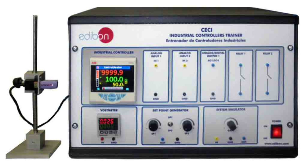
The Industrial Controllers Unit, "CECI", is based on a modular design structure whose functionality is divided into different modules toallow the student a better understanding of the unit. The modules included in the unit are: industrial controller, digital voltmeter, set pointgenerator, system simulator and communication module.
研究室
関連ニュース
概要
The Industrial Controllers Unit, "CECI", is based on a modular design structure whose functionality is divided into different modules toallow the student a better understanding of the unit. The modules included in the unit are: industrial controller, digital voltmeter, set pointgenerator, system simulator and communication module.
- Industrial Controller: the controller has two analog inputs and analog/digital output. The analog inputs plugs are used to connectthe process value (PV) and set point value (SP) signals. The analog/digital output plug is used for the output process signal (OP). The controller also has two configurable relays. In addition of configuration through the software, the industrial controller parameters canalso configured with the industrial controller front panel.
- Digital Voltmeter: this module allows visualize the amplitude of a dc signal.
- Set Point Generator: this module allows to generate a step signal by switching between two different selectable voltages. The voltage levels can be adjusted using two potentiometers.
- System Simulator: this module represents a first order lag system. The time constant of the system is 20 s. The gain of the system canbe adjusted using the corresponding potentiometer.
- Communication module: this module consists of an infrared to USB adapter mounted in a mobile structure. The structure allows us tofix the adapter in order to align it with the controller.
The software provided with the "CECI" unit is the commercial software ABB device type manager (DTM), configuration software for Control Master industrial controller versions. This software allows students learn with real industrial controller software.
The software allows selection of type of control, industrial controller parameters, setting of alerts and alarms, type of system loop, etc. The access to configuration of different parameters is through a comprehensible Blocks scheme of the system process.
演習と指導の慣行
マニュアルに含まれるガイド付き実習
- Installation, connection and familiarization with the software.
- Study of the transfer function (static and dynamic).
- Familiarize with the Set point generator, generation of a square signal using two analog signals.
- Familiarization with the navigation of an industrial controller (operator page screen, trend display screen, etc).
- Step-response of a first order system.
- Configuration of analog inputs/outputs signals of the industrial controller (electrical range, engineering units, fault detector, etc).
- Manual control of a first order system using an industrial controller (open-loop).
- Automatic PID control of a first order system using an industrial controller (closed loop).
- Obtaining the PID parameters automatically using autotuning.
- Setting alarms and diagnostics generation.
- Setting of an industrial controller using the front panel (configuration level, parameter level, operation control level, etc.).
- Remote setting of an industrial controller using the configuration software (configuration level, parameter level, operation control level, etc.).
利用可能な類似の機器
フィールドバスアプリケーション用演習装置
制御装置チューニング演習装置
補完的な機器
産業用コントローラーネットワーク
制御装置チューニング演習装置
フィールドバスアプリケーション用演習装置
品質

アフターサービス

 クッキーの設定


