AEL-LPSG 低出力同期発電機の適用

LOW POWER SYNCHRONOUS GENERATORS APPLICATION - AEL-LPSG

革新的なシステム

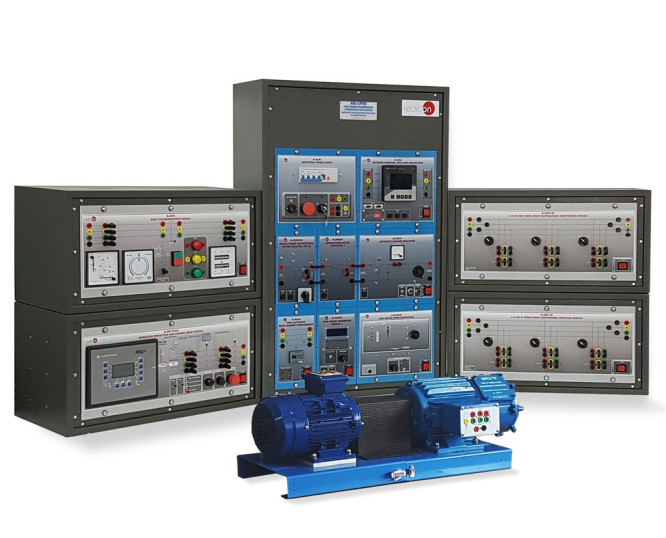
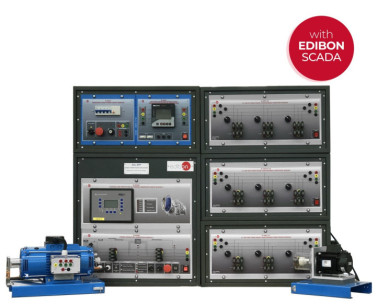
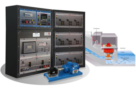
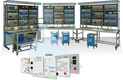
The Low Power Synchronous Generators Application, "AEL-LPSG", has been designed by EDIBON to study the procedure and the maneuvers required for the synchronization of synchronous generators with the grid, with the aim of delivering the generated energy as done in actual power plants.

一般的な説明を表示

関連ニュース

概要

The Low Power Synchronous Generators Unit, "AEL-LPSG", has been designed by EDIBON to study the procedure and the maneuvers required for the synchronization of synchronous generators with the grid, with the aim of delivering the generated energy as done in actual power plants.

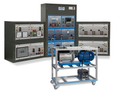
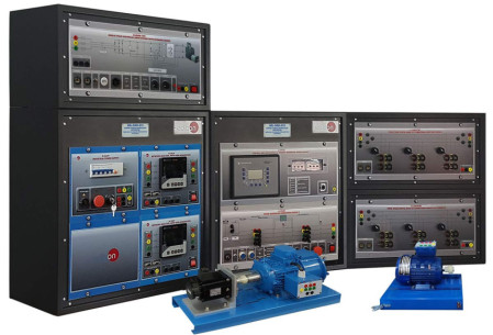
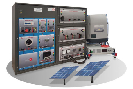
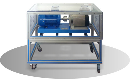
The "AEL-LPSG" unit allows the user to go deeper into the working principles and control of synchronous generators to show the step-by-step synchronization process with the electrical grid. For this, the unit includes a synchronous generator coupled to a motor (which will act as driving force, simulating a turbine) along with a series of modules such as a single-phase transformer, an AC/DC converter and a voltage regulator which form the generator excitation circuit. It is also included a motor controller for the turbine-generator speed control, an analog overcurrent relay as grid protection device and a network analyzer to monitor the generation electrical parameters such as the active and reactive powers generated, frequency, voltage, current, power factor, etc.

This unit offers two possibilities regarding the generation group control. The first option, the manual control of synchronous generators kit, includes a PWM signal generator module for the control of the synchronous generator excitation current (and therefore the output voltage). This enables the user to carry out the no load, under load and short circuit test aimed to obtain the characteristic curves and the equivalent circuit of the synchronous generator. This kit also includes a synchronization module which will allow the user to monitor and carry out manually the synchronization process. For that, the synchronization module has two analog voltmeters (grid and generation voltage), two frequency meters (grid and generator frequency), a digital synchroscope and two push-buttons for closing and opening the synchronization switch.

The second option, the synchronous generator automatic control module, offers the possibility to control automatically every electrical and mechanical parameter of the generator-turbine group. The most significant control parameters are the turbine speed, the generator frequency, the excitation current, the voltage at the generator output and the active, reactive and apparent powers. Moreover, this control module is at the same time an advanced protection for generators and turbines. It meets the ANSI standards regarding the protection parameters for generators and turbines (ANSI 81O, ANSI 81U, ANSI 59, ANSI 27, ANSI 50/51, ANSI 32R/F, ANSI IOP 32, ANSI MOP 32, ANSI 46, Voltage Asymmetry, Generator Ground Fault, Phase Rotation, ANSI IEC 255, Generator Lagging Power Factor, among others). It is required to acquire at least one of the two previously described options to be able to work with the modules included in the base unit.

In order to acquire a greater experience with the study of synchronous generators, it is recommended to acquire a set of resistive and inductive loads with the aim of studying the island operation of synchronous generators (isolated from the national grid). These loads will allow the user to go deeper into the basic concepts about the behavior of synchronous generators working under load, such as generation and demand in isolated systems, voltage drops or the output voltage control by means of the excitation current regulation.

It is also recommended to acquire a kit for the study of faults in synchronous generators, consisting of an advanced differential protection relay with configurable numerical programming which allows showing the features of three-phase differential protection, two power switch modules as interrupting devices, a fault injection module for the injection of single-phase, two-phase or three-phase, to earth, faults and a module with three-phase inductances as buffering element for the faults at the generator induced side. In addition, it is recommended as well a rotor protection module for the study of faults at the synchronous generator excitation side and a three-phase harmonic filter for the reduction of the harmonics resulting from the regulation of the generator excitation current.

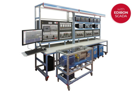
The "AEL-LPSG" is one of the most complete and versatile units regarding the in-depth study of synchronous generators, both in island and parallel to grid operations. Furthermore, it is compatible with any type of energy transmission line which makes it possible to study the impact of synchronous generators on real grids, analyzing events such as power transfer among several machines working in parallel, sudden decouplings and its consequences and endless maneuvers related to electric generators. Finally, for the most optimal management of the unit, it is recommended the Data Acquisition and Energy Management Software, "EMG-SCADA".

This awesome tool allows the user to monitor all the curves for the grid and generator electrical parameters, watch the voltage dips, energy losses in transmission lines and voltage drops. In addition, it allows saving all the acquired data to watch and compare it later. It is possible to see clearly and with accuracy the effects of reactive power compensation on the monitored power curves, maximum and minimum energy demand, load unbalances and the variation of the power factor in the nodes of the system.

演習と指導の慣行

マニュアルに含まれるガイド付き実習

Practical possibilities in case of acquiring the kit for the manual control of the Turbine-Generator group, LPSG-K1 :

  1. Manual control of the generator-motor group frequency .
  2. PWM signal generation and duty cycle regulation.
  3. Assembly of the self-excited static excitation circuit.
  4. Manual control of the synchronous generator voltage by means of the excitation current control through PWM signals.
  5. Startup of the synchronous generator under no load.
  6. Manual synchronization of the synchronous generator with the grid.
  7. Synchronization through the dark lamps method.
  8. Synchronization through the bright lamps method.
  9. Synchronization through two dark and one bright lamps method.
  10. Monitoring the power flows injected into the grid.
  11. Active power (P) and reactive power (Q) generation control in synchronism with the grid, by means of the generator frequency and excitation current control respectively.
  12. No load test of the synchronous generator. N-MED11 and N-MED22 modules are required.
  13. Empirical obtaining of the synchronous generator no load characteristic, E= f (Iex). Lineal and saturation zone. N-MED11 and N-MED22 modules are required.
  14. Short-circuit test of the synchronous generator. N-MED11 and N-MED22 modules are required.
  15. Empirical obtaining of the synchronous generator shortcircuit characteristic. N-MED11 and N-MED22 modules are required.
  16. Computation of the Poitier's diagram. N-MED11 and N-MED22 modules are required.
  17. Computation of the synchronous generator impedance. N-MED11 and N-MED22 modules are required.
  18. Determining the equivalent circuit of the synchronous generator. N-MED11 and N-MED22 modules are required.
  19. Computation of the synchronous generator capacity limits. N-MED11 and N-MED22 modules are required.
  20. Control logic circuit for the protection of the synchronous generator in synchronism with the grid.
  21. Measurement of the harmonic generation caused by the power elecronic.

Practical possibilities in case of acquiring the module for the automatic control of the Turbine-Generator group, N-ERP-PGC01:

  1. Automatic control of the generator-motor group frequency.
  2. Assembly of the self-excited static excitation circuit.
  3. Adjustable automatic control of the synchronous generator output voltage.
  4. Automatic synchronization of the synchronous generator with the grid.
  5. Monitoring the power flows injected into the grid.
  6. Adjustable automatic control of the active power injected into the grid.
  7. Control logic circuit for the protection of the synchronous generator in synchronism with the grid.

Practical possibilities in case of acquiring the kit for the island operation of the generator, RL-KIT-1:

  1. Island operation with manual/automatic control of the generator-motor group.
  2. Study of the generation and demand in isolated systems.
  3. Study of the votlage drops in sycnhronous generators and compensation through manual/automatic regulation of the generator excitation current.
  4. Test for obtaining the external characteristic of the synchronous generator, V = f (I).

Practical possibilities in case of acquiring the kit for the study of faults in sycnhronous generators, GFS-KIT-1:

  1. Overcurrent protection test with the generator in synchronism with the grid.
  2. Overcurrent protection test with the generator in island operation.
  3. Differential protection relay setting.
  4. Study of the scheme for the differential protection of the synchronous generator in case of fault.
  5. Study of single-phase, two-phase, three-phase, to earth, with and without impedance faults.
  6. Study of the differential protection against instantaneous overcurrent (50P1H).
  7. Study of the differential protection against definite time overcurrent (50P1).
  8. Study of the differential protection against inverse time overcurrent (51P1).
  9. Study of the differential protection against definite time negative sequence current (50Q1).
  10. Study of the differential protection against inverse time negative sequence current (51Q1).
  11. Study of the differential protection against instantaneous residual current (50N1H).
  12. Study of the differential protection against definite time residual current (50N1).
  13. Study of the differential protection against inverse time residual current (51N1).
  14. Transient analysis of fault injection by means of the differential relay manufacturer's software.

Practical possibilities in case of acquiring the rotor earth-fault protection module, N-REP:

  1. Study of the scheme for the rotor protection of a synhcronous generator in case of fault.
  2. Rotor earth-fault protection test.

Practical possibilities in case of acquiring the three-phase harmonic filter, N-THF01:

  1. Study and monitoring the harmonics generation.
  2. Harmonic reduction by means of a three-phase passive filter.

Practical possibilities with the recommended additional element Three-Phase AC/DC Electronic Load of 1800 W, "TPEL/1800W":

  1. Study of different dynamic load curves developed by means of the electronic load.
  2. Island operation with manual/automatic control of the motor-generator group with electronic load.
  3. Study of generation and demand in isolated systems with electronic load.
  4. Study of voltage drops in synchronous generators and compensation by manual/automatic regulation of the generator excitation current under electronic load.

Practical possibilities with the recommended additional element Dynamic Load Kit 1 "SVC-K3":

  1. Modulation of a load curve consisting of two peaks, a valley and a base load by means of a magnetic dust brake.
  2. Island operation with manual/automatic control of the motor-generator set with dynamic load.
  3. Study of generation and demand in isolated systems with dynamic load.
  4. Study of voltage drops in synchronous generators and compensation by manual/automatic regulation of the generator excitation current under dynamic load.

Practical possibilities with the additional recommended element Data Acquisition and Energy Management Software, "EMG-SCADA":

  1. Remote manual control of voltage and frequency of the synchronous generator.
  2. Remote automatic control of voltage and frequency of the synchronous generator.
  3. Remote automatic synchronization operation of the synchronous generator and the grid.
  4. Real time monitoring of the induction generator frequency, current and voltage values and waveforms.
  5. Real time monitoring of the generated active, reactive and apparent powers.
  6. Visualization of the phasor diagrams of the system electrical parameters.
  7. Data saving and storage.
  8. Comparison of the obtained results.
もっと見る

より実用的な練習をして、ユニットを完成させる

  1. Several other exercises can be done and designed by the user.

利用可能な類似の機器

品質

アフターサービス

リクエスト情報