ELT 전송 라인 장비
혁신적인 시스템
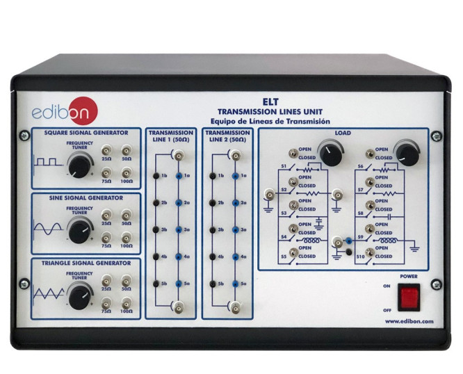
The Transmission Lines Unit, "ELT", has been designed by EDIBON to study a standardized coaxial line to analyze realistic measurements. The unit is fully provided with a set of practices that allow the student to study and to understand the diverse techniques to testing the signal transmission in a line (in steady-time and in time domain) and the techniques to characterize a transmission line (mismatches, variation of impedances, discontinuities, etc).
실험실
관련 뉴스
일반적인 설명
The Transmission Lines Unit, "ELT", has been designed by EDIBON to study a standardized coaxial line to analyze realistic measurements.
The Transmission Lines Unit "ELT" has been designed as integrated unit for help the student to understand the basic principles of thetransmission line measurement theory.
The coaxial cable is the most common way to build a transmission line, because they allow a reliable communication from low frequencies to microwaves frequencies. The "ELT" has been designed to study a standardized coaxial line to analyze realistic measurements.
The unit is fully provided with a set of practices that allow the student to study and to understand the diverse techniques to testing the signal transmission in a line (in steady-time and in time domain) and the techniques to characterize a transmission line (mismatches, variation of impedances, discontinuities, etc).
The unit is divided into different blocks: Signal generators, Transmission lines and Loads.
- Signal Generators block:It contains a group of signal generators in order to study the behaviour of different types of signals. Each signalgenerator contains an encoder to change the signal frequency and four BNC connectors with different output impedance. There are threetypes of generators: Square Signal Generator, Sine Signal Generator and Triangle Signal Generator.
- Transmission Line block: It contains two transmission lines made each one of 40 m. of cable RG-174, in order to study an individualtransmission line of 40 m. or 80 m. transmission line with the sum of both lines. The two transmission lines contain two BNC connectorsat the beginning and the end of the line and five test points with 10 m. of coaxial cable between each other. The first and the last testpoints are internally connected to the nearest BNC connectors.
- Load block: This block contains two sets of loads, to configure the different termination loads or to configure the different discontinuitiesin the transmission line. The two sets of loads have a variable resistance, a fixed resistance, a capacitive load, an inductive load, a shortcircuit, etc. These different loads are set with an associated switch with each one.
연습 및 가이드
매뉴얼에 포함 된 가이드 실기 연습
- Familiarization with the unit.
- Analysis of the attenuation measurement along the line withSine signal.
- Analysis of the attenuation and distortion measurements alongthe line with Triangle signal.
- Analysis of the attenuation and distortion measurements alongthe line with Square signal.
- Calculation of insertion losses.
- Measuring of VSWR of a matched and mismatched load andthe conversion in return loss and reflection coefficient.
- Calculation of line impedance and reflection coefficient withthe Smith chart.
- Analysis of the velocity of propagation with time domainreflectometry (TDR).
- Measuring the length of a line with TDR.
- Use TDR to identify faults in the transmission line.
- Use TDR to identify the differences between matched loadsand mismatched loads and study of the transmission lineimpedance.
- Use TDR to identify the differences between inductive andcapacitive loads.
- Finding discontinuities on a line with TDR.
보완 장비
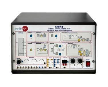
Digital Modulations Unit
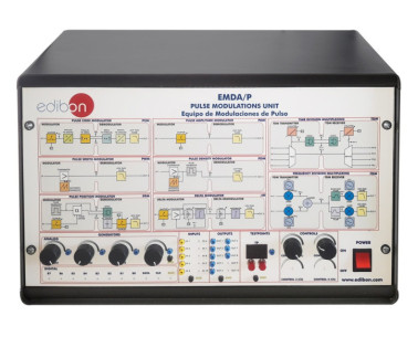
Pulse Modulations Unit
Computer Controlled Teaching Unit for the Study of Digital Signal Processing
품질

판매 후 서비스

 쿠키 기본 설정

