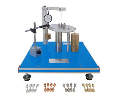
MVV Оборудование для консольных балок
ИННОВАЦИОННЫЕ СИСТЕМЫ
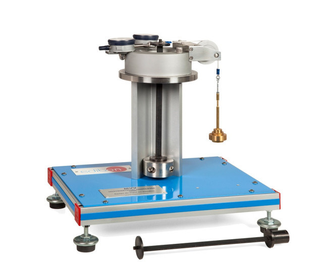
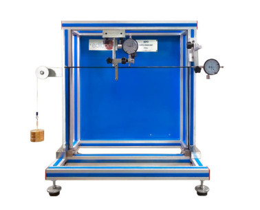
The Unsymmetrical Cantilever Unit, "MVV", has been designed by EDIBON to demonstrate the unsymmetrical bending of beams.
Расширения
ЛАБОРАТОРИИ
НОВОСТИ ПО ТЕМЕ
ОБЩЕЕ ОПИСАНИЕ
The system consists of a vertical cantilever rigidly clamped at its lower end to the main column which is attached to a rigid structure. Beams of different sections may be used.
A loading head, located at the upper end of the column, can rotate freely around the vertical axis of the beam at 15° intervals. A horizontal load may be applied to the free end of the beam by means of a cord attached to the beam and passing over a pulley mounted on the rotating head.
The Δu and Δv deflections of the beam are measured by means of two dial gauges mounted perpendicularly to each other on the head. To compensate any lateral deflection of the beam, the line of action of the applied load can be adjusted by lateral adjustment of the load pulley.
Two steel beams are supplied, one with rectangular section and the other one with L shape section.
УПРАЖНЕНИЯ И ПРИМЕРЫ С ИНСТРУКЦИЯМИ
РУКОВОДСТВО ПО ПРАКТИЧЕСКИМ УПРАЖНЕНИЯМ ВКЛЮЧЕНО В РУКОВОДСТВО ПОЛЬЗОВАТЕЛЯ
- Determining the deflection of the beam depending on theintensity of the force applied.
- Determining the deflection of the beam depending on thedirection of the force applied.
- Determining the Δu and Δv deflections at free ends of cantilevers.
- Studying the deflections at two planes, for several sections.
- Determining deflections for different angles of force applied.
- Studying the rigidity variation.
- Determining the position of the torsion centre of the beam (Itrequires the optional accessory MVV/1).
ДОПОЛНИТЕЛЬНОЕ ОБОРУДОВАНИЕ
Оборудование для подвесного моста
Оборудование для параболической арки
Оборудование для трехшарнирной арки
Оборудование для изучения сил в простой ферменной конструкции (простые фермы)
Оборудование для изучения сил в различных сборках плоских ферм
Оборудование для изучения сил в статически неопределимых фермах
Оборудование для изучения деформации в фермах
Оборудование для изучения толстостенных цилиндров
Оборудование для двухшарнирной арки
Оборудование для изучения портальной конструкции
Оборудование для проверки гипотез напряжений
КАЧЕСТВО

ПОСЛЕПРОДАЖНОЕ ОБСЛУЖИВАНИЕ

 Настройки cookie

